This thread has been locked.

If you have a related question, please click the "Ask a related question" button in the top right corner. The newly created question will be automatically linked to this question.

LM5176: abnormal behavior for 18V to 20V DC/DC converter

Part Number: LM5176

Hi, my customer is using LM5176 for type C power. The schematic is as below

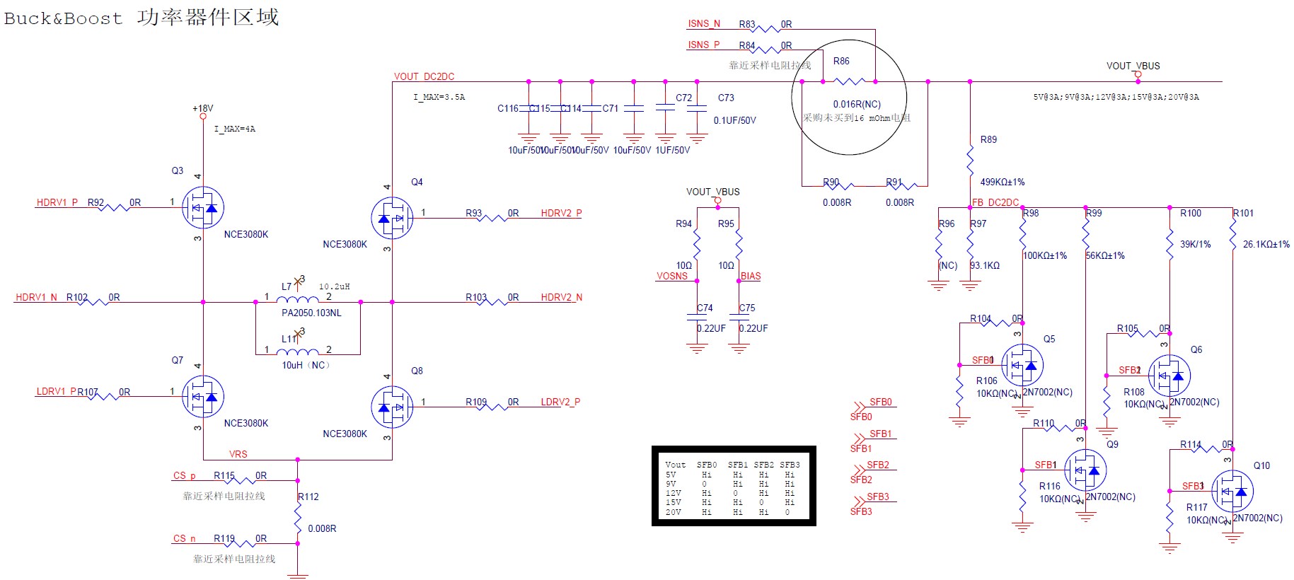
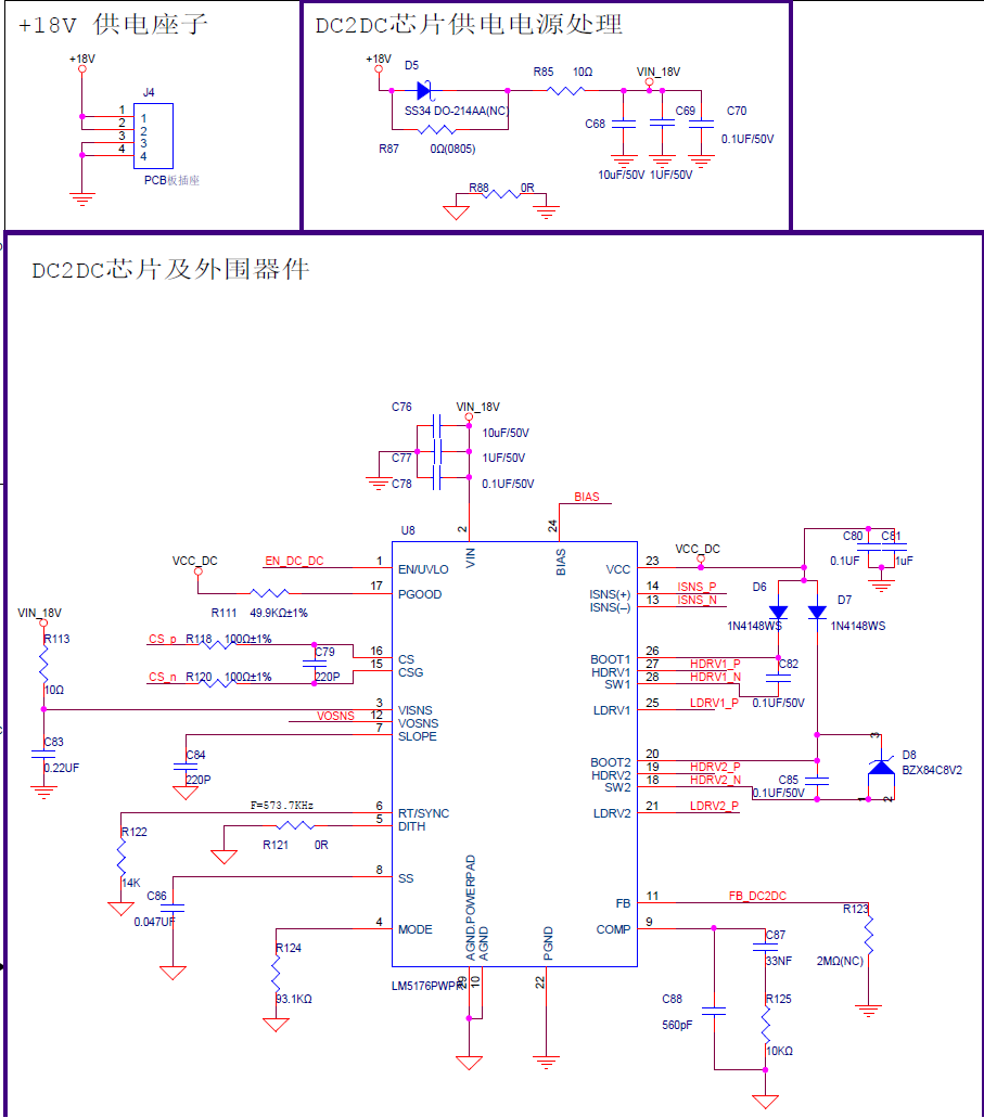
The input is 18V, the output could be 5V, 9V, 12V, 15V, 20V.

It can work well at 5V, 9V, 12V output. But can't work well at 15V, 20V output.

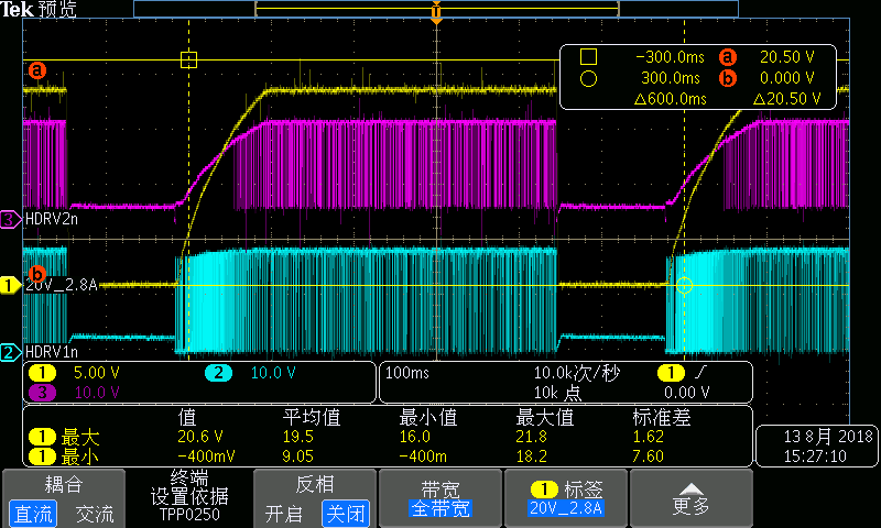
When configured 20V, 0A output, the waveform is as below: yellow- 20V output, purple- HDRV2_N, blue- HDRV1_N.

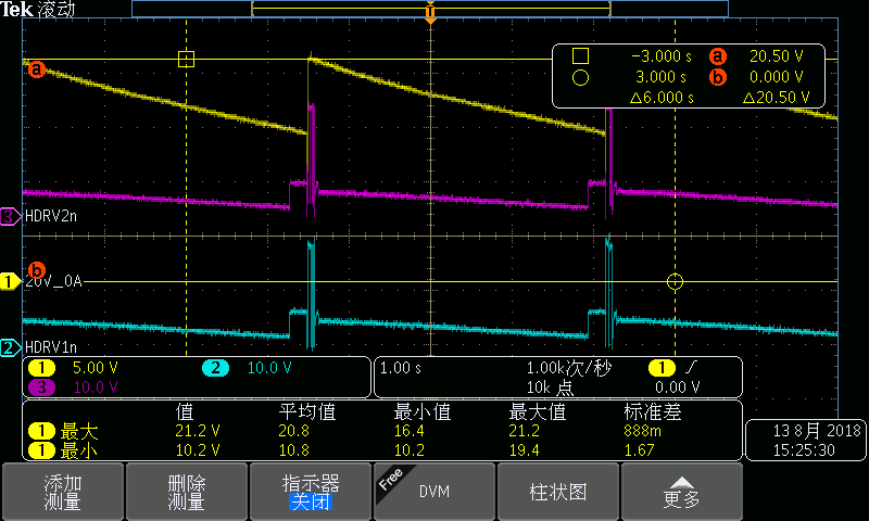
When configured 20V, 2.8A output, the waveform is as below: yellow- 20V output, purple- HDRV2_N, blue- HDRV1_N.
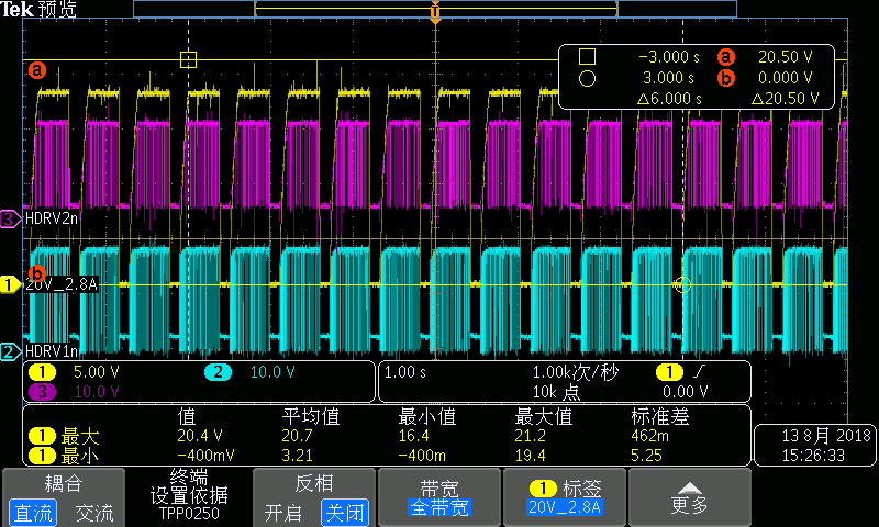
After zoom in,

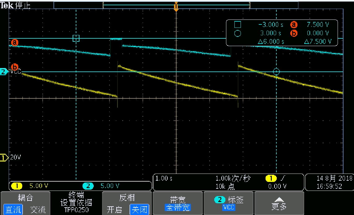
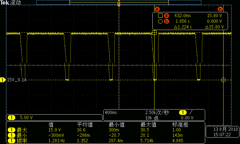
For 15V 0A output, it's also abnormal, the output waveform is as below:

For 15V 0.1A output, the output waveform is as below:

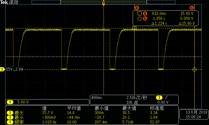
For 15V 2.8A output, the output waveform is as below:

What may cause this abnormal and how to fix it?

  • The switching frequency is set to be 573kHz, and the current sense resistor R86=0.016Ohm.

    I guess it's caused by protection of the device. I will let the customer check what caused the protection.

    But no idea how to fix it.

  • Hi Howard,

    Have you double checked the component values? Please use the LM5176 quick-start calculator to do this. It looks like the average output current sense resistor or peak inductor limit is causing the LM5176 do go into current limit. In the calculator please start by checking the  design where the output is 20V and the input voltage is the minimum. This will help to size the components correctly.

    -Garrett

  • Hi,

    I have a question about VCC.

    According to datasheet, VCC should remain constant as long as Vin and EN/UVLO is constant, even if overcurrent or thermo shut down happens, right? 

    We've observed Vin(18V) and EN/UVLO(3.3V) is constant.

    But we can observe VCC drop as below (blue line), why?

    18-20V, 0A waveform:

  • Hi Howard,

    Yes when the UVLO pin is above the standby threshold the VCC rail should be constant voltage. Please check to ensure if the EN/UVLO pin as above the standby threshold. Also please double check to ensure that the VCC rail is not being current limited.

    If you have more questions please contact me directly.

    -Garrett
  • Thank you.

    We are sure that EN/UVLO is above the standby threshold.

    But how can I check if VCC rail is current limited or not? What may cause the current limit?

  • Howard,

    This is based on the MOSFET and switching frequency that are being used.

    IVCC = QGtotal*fsw+5mA

    IVCC is the current drawn by the VCC rail
    QGtotal is the gate charge of all the MOSFETs added together
    fsw is the switching frequency
    5mA is just a little bit of margin

    The IVCC current must be less than the 65mA specified in the datasheet.

    -Garrett
  • Thank you.
    But personally I don't think IVCC will be a problem.
    Because they use four identical MOSFETS in the circuit, and the switching frequency is constant with 5V, 9V, 12V, 15V, 20V output.
    If IVCC doesn't cause problem at 5V, it should work well at 15V, 20V output, too.

    I have applied EVM for the customer to test to see if they can revise their circuit based on our EVM.