Because of the Thanksgiving holiday in the U.S., TI E2E™ design support forum responses may be delayed from November 25 through December 2. Thank you for your patience.

This thread has been locked.

If you have a related question, please click the "Ask a related question" button in the top right corner. The newly created question will be automatically linked to this question.

TPS1H000-Q1: TPS1H000-Q1

Part Number: TPS1H000-Q1

Hello,

Currently, i use a TPS1H000 component to limit current on an output signal of an electronic application.

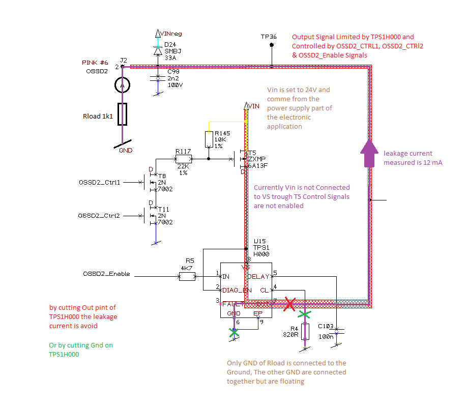
During a leakage current measurement test of this application, we have notice that leak current went back through the out pin of TPS1H000 up to the gnd of the application (trough GND and CL pin of TPS1H000).

This problem is solved if we cut CL and GND Pin of the TPS1H000 or simply by cutting is output pin. (see raw schematics in attachement)

Could you provide me an explanation about this event and a recommended schematic protection against it?

Thank you in adavance

Best RegardsSchematic Leak Current Test.pdf

  • Hello,

    Would you please give more detail about the leakage current you mentioned. Where do you apply the voltage for this leakage test? and what is the value of the applied voltage? what is the value of the leakage current?

    Regards

  • Dear Mahmoud, see in attachement my answer

    Thank you for your help,

    best regards

    Romain

  • I have solve it ,
    by adding a diode on GND of TPS1H000 but i can't explain what it append here!
    i will be interested by an explanation if you find one.
    Thanks in advance
    Regards
    Romain
  • Hello Romain,

    I understood the leakage takes place when you apply voltage on Device GND and a resistor connect to output. By doing that a current flows from GND to output. If this is the case, it is due to reverse bias of the substrate I believe. Adding a diode in the ground will block the current from going through the substrate.

    Regards

  • Good morning Mahmoud,

    To carry on about this topic, it is a big problem.
    If this component is used in safety device, the leakage current is sufficient to activate an output device like a relay.

    Do you mention this here:
    "
    7.3.5.2.2 Output Off
    ...
    There is always a leakage current I (ol,off) present on the output due to the internal logic control path or external
    humidity, corrosion, and so forth. So an external pullup resistor is recommended to offset the leakage current
    when an open load is detected. The recommended pullup resistance is 15 kΩ.
    "

    Thank you in advance,

    Best regards,
    Nicolas.
  • Hello Nicolas,

    That is right the pull up resistor Rpu forms a voltage divider with the load impedance Rload in off satate. The voltage across the load is [ Vsupply x Rload/(Rpu + Rload)]. It depends on the ltype of load if this voltage is enough to bias it or not.

    Regards
  • Thank you Mahmoud for your answer.

    But it is not solved the problem :-(

    When we measure the resistor between Vout and GND, without power (Vs not connected), it gets 22 Kohm.
    It should be greater.
    In this case, a current can be rejected by Vout and activate a simple safety relay.

    Where is the measure of this resistor in the datasheet?

    Thank you in advance,

    Best regards,
    Nicolas.
  • Hello Nicolas,

    Measuring the resistance from output to GND does not give the right information. That is because there is the FET back diode from VOUT to VS. The resistance from VS to GND is counted in the measurment as well if the supply is floating. The right measurement is described in the datasheet parametric table page 6 as I(ol,off). This leakage current is 70uA max. I hope that answers your question.

    Regards