This thread has been locked.

If you have a related question, please click the "Ask a related question" button in the top right corner. The newly created question will be automatically linked to this question.

TPS92692: low dimming flicker question

Part Number: TPS92692

Hi 

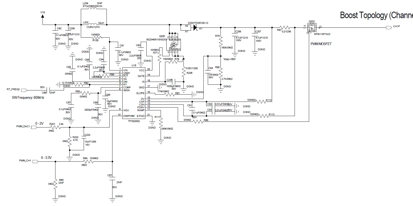
I  use TPS92692 as booster to light up 15 LEDs. I have low dimming requirement and need LED current low to 0.1mA. Hence I set IADJ voltage to 10mV and use PWM dimming. PWM duty may change from 1/50 to 50/50. I found LED may flicker from PWM 1/50 to 7/50 and I measure the inductor current as figure1. I also design TPS92602 for this low dimming application but TPS92602 doesn't have flicker issue. The inductor current as  figure2. The inductor current very different in low dimming and could TPS92692 low dimmig behavior like TPS92602?

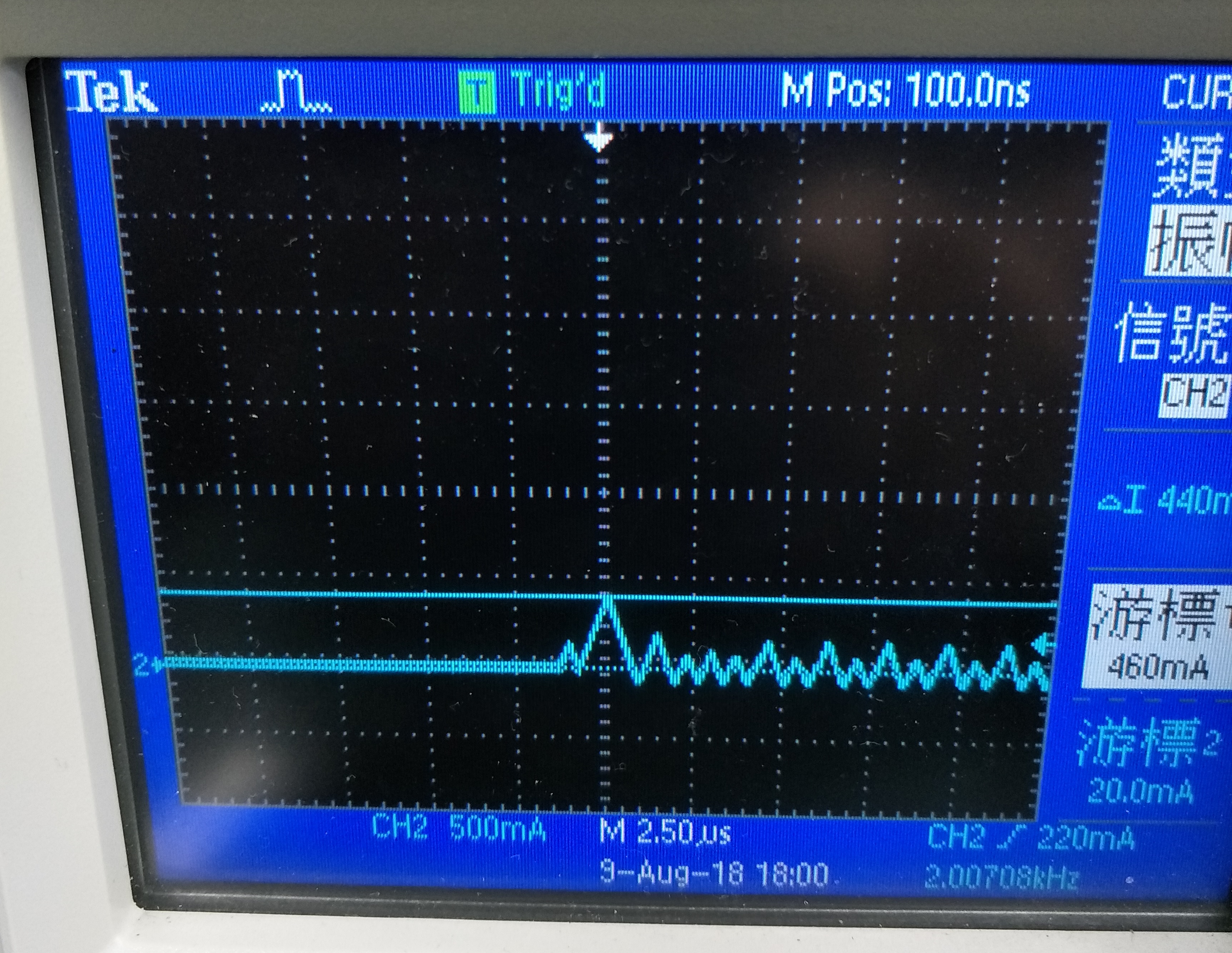
Figure 1. TPS92692 inductor current

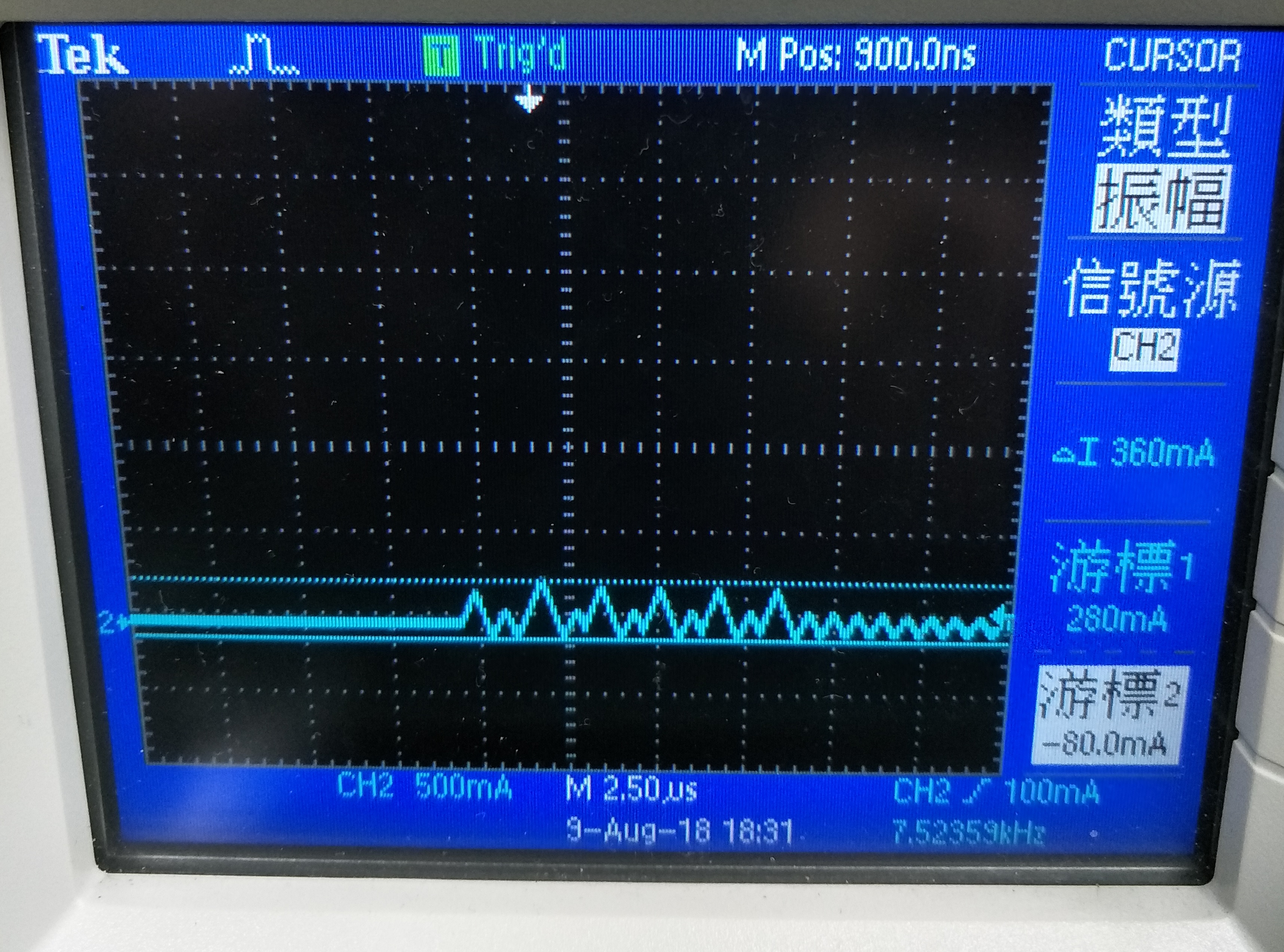
Figure 2. TPS92602 inductor current

Thanks

Best regards

Janson

  • Hi Janson,

    From section 8.3.9 of the specification for TPS92692: The IAJD input range is 140mV to 2.25V. So when you using 10mV input to IADJ you are not within the range that the TPS92692 required.

    Are you wanting to run 0.1mA average current on the LED with PWM? Or are you trying to run 0.1mA when PWM are ON so for 10% duty cycle the average is 0.01mA? For low current the external components have to be sized correctly also. Looking at the current on both of your scope capture they both do not look stable to me. It should be one high peak for the first pulse then all the pulses after should be the same.
  • Hi Tuna :

    Because analog dimming can not achieve my low dimming requirement, so I use PWM dimming to lower LED when IADJ voltage is lowest. IADJ = 140mV . My requirement is 0.1mA average current. "For low current the external components have to be sized correctly also" could you explain more detail? Why first pulse need high peak current?

    Best regards

    Janson

  • Hi Janson,

    For that low of a current it might be best to use a boost regulator then a linear driver.  The TPS92692 is designed to run higher current than your 0.1mA so the current sensing and design is not optimized for that.

    Thanks Tuan

  • Hi Tuan :

    My TPS92692 circuit work on boost topology. Does TI have suitable product for 0.1mA LED current application? 

    Best regards

    Janson

  • Hi Janson,

    I handle the TPS92692 but not other linear LED driver products so I will need to do some searching around to see if we can help you with this.

    Thanks Tuan

  • Hi Janson,

    Are you using the TPS92692 evaluation board or are you doing your own design? In the mean time can you send your current schematic that you have of the TPS92692 to me so I can review it.

    Thanks Tuan
  • Hi Tuan :

    I design my own TPS92692 circuit base on EVB schematic. Below is my schematic.

  •  Hi Jason,

    Based on your schemactic, you probably have gone thru all the calculations already to use 0.2 Ohm for RCS (R87).  The key is to raise RCS as high as possible and still be able to get the peak current with IADJ at 2.25V based on the below LED Current programming from the data sheet.  The main thing we should try to do is to get as much signal with the 0.1mA as possible.  For your existing design, the current is 5mA at 1/50 duty cycle that gives 0.1mA.  With 5mA thru 0.2 Ohm you are only getting 1mV of signal.  This is too low of signal.

    The other is to use the lowest DIM/PWM frequency as possible when dimming and this will give us the most time for the loop to catch up and be stable.  What is the DIM/PWM frequency are you commanding?  You mentioned 1/50 as the duty cycle...Is this a system constraint or you can use lower duty cycle like 1/100? 

    Can you also give me your requirements with input voltage (V19 from schematic), forward votlage of the LED's, max DC current you are trying to command with IADJ and what is the application for this design (end product)?

    Thanks Tuan


  • Hi Tuan :

    Thanks for your feedback, it's very useful for me. My DIM/PWM frequency is 2KHz. LED strip VF is 31V to 58V. Max DC current is 750mA. My LED product application is for Aquarium Light.

    Best regards

    Janson

  • Hi Jason,

    I did not get the input voltage range from you and I would like to get this to do a full check up of your design.

    You mentioned that you are PWM'ing at 2KHz...Can we lower this down to 200Hz and PWM down to 1% duty cycle or so.  With this you can increase the IADJ current higher to 10mA and get your 0.1mA average from dimming.  We are trying to increase the current as high as possible to increase signal to noise.  If you have flicker then stay at 1% duty cycle and increase the current with IADJ until you don't have any flicker...Let me know what that current is. 

    With COMP cap of 0.1uf the control loop should be stable but you should do some loop stability testing like sweeping the loop for gain and phase margin or even step response to see how stable your loop is?   

    Thanks Tuan

  • Hi Tuan :

    Input voltage is from 18.5V to 19.5V. I can modify PWM frequency but it need some time. In current design, led current need up to 0.4mA then stop flicker when PWM duty 1%.

    Thanks

    Best regards

    Janson

  • Hi Jason,

    For the 19V input voltage and 600KHz switching frequency, the RIS (R205) should change to 0.130 Ohm and RSlope (R81) should be 69.8K.  The power disipation on R205 is about 0.25W so use appropriate rating power for that. 

    You can also try to go lower than 1% dimming once you get your PWM frequency change to 200Hz.

    Thanks Tuan

  • Hi Tuan :

    Change R205 to 0.13 ohm can improve low dimming flicker issue, but the MAX output current will drop to 70mA when output current bigger than 595mA. So I change R205 to 0.1 ohm then the output current can meet 750mA requirement and flicker also improve. It's seems TPS92692 also senses MOS current for internal control, not only over current protection.

    Thanks

    Best regards

    Janson

  • Hi Jason,

    The TPS92692 has an inner peak current control loop so R205 is feeding back the peak current for part of the control loop.  The low current requirement really tests the signal to noise of the design.  By changing R205 to 0.1 Ohm you are increasing the signal by a factor of 2 for the inner loop. 

    You need to work on changing the PWM dimming frequency from 2KHz to 200Hz next and see if you can improve both the flicker and the low end current.  Try going as low as you can on the PWM duty cycle even below 1% and test until you see flicker and let me know what that is.  Remember to also look at the LED current with a current probe like you did before and let me see that signal.  It's important to look at the current signal since this will tell us how stable the low end current is.

    Thanks Tuan

  • Hi Jason,

    I have not heard back from you so I believe you may have solved the issue.  The thread will close now but will reopen if you reply.

    Thanks Tuan