This thread has been locked.

If you have a related question, please click the "Ask a related question" button in the top right corner. The newly created question will be automatically linked to this question.

LM3150: Wrong switching frequency

Part Number: LM3150
Other Parts Discussed in Thread: COT,

I calculated value of Ron=224888.67 Ohm resistor by the equation (26) from datasheet for frequency 200 kHz, input voltage Vin=12V, output voltage Vout=5V. When I ran this controller (LM3150MH) with resistor Ron=220 kOhm the switching frequency was 250-260 kHz

The required value of switching frequency was reached with Ron=300 kOhm.

This value is critical for me because the lower bound of input voltage is 6V. Because of this, to get a stable operation over a wide temperature range, I need to make toff more than 725 ns (datasheet value).

Why there is such large difference in the nominal value of the resistor calculated by the equation with the real value?

Whether this value will differ on different controllers in such a wide range?

Is there a way to correctly calculate this resistor?

  • Egor,

    I've gone through your calculations and came to the same conclusion using equation 26.

    I also tried out equation 1 and got: (Vout=5V, Fs=200kHz) Ron=250k which is closer to your observed value than what we calculated using equation 26. This discrepancy is because eq 1 is a general equation where the other is more specific. I would expect the more specific to be closer to board tests but it's tough to predict the exact frequency of a COT.

    This discrepancy between calculated and board test seems larger than expected. Is the controller operating properly? Is the SW node a constant rectangular wave with constant duty cycle? What load are you testing at?

    This frequency should be pretty consistent between your LM3150 boards. The large discrepancy is not caused by tolerances in the IC so you should not expect to see a large variation between boards in terms of switching frequency assuming the board is stable and working properly.

    You used the best method of calculating resistors but COTs are hard to predict perfectly, plus there are board variations between applications. So the only real way to know the exact frequency is to build it.

    -Sam
  • Sam, thanks for your reply.

    I really observed the effect you described when connecting a ceramic capacitor 10 uF parallel to the output capacitor of the LM3150 without the appropriate compensation scheme, as well as an with incorrect path of current flow from shottky diode in parallele with low-side mosfet. But during the main testing the controller operated property and SW node was a constant rectangular wave with constant duty cycle.

    To confirm this, I attached the waveforms were obtained when the LM3150 was started with an input voltage Vin=12V; Load current I_load=1A (The load consists only of resistors with a total rating of 5 Ohm ), output voltage Vout=5V

    Waveform on SW node with Ron=220 kOhm

    Waveform on high and low transistors with Ron=220 kOhm


    Waveform on SW node with Ron=250 kOhm


    Waveform on high and low transistors with Ron=250 kOhm


    Waveform on SW node with Ron=300 kOhm


    Waveform on high and low transistors with Ron=300 kOhm


    If the value of the on time resistor is not significantly different on different chips, then this problem becomes less significant, but still I would like to be able to correctly calculate the switching frequency at the design stage.

  • Egor,

    Those are some clean-looking waveforms. Thanks for sharing.

    Another reason would be if efficiency was low. Toff would shorten to compensate for the lost energy but the duty cycle looks reasonable for 12VIN, 5VOUT.

    The last waveforms show a Ton of 21us which correlates to an Ron of 250k but you have 300k. VIN is 12V but is there lots of ripple?

    And does this frequency discrepancy change with load?

    I understand the desire to be able to rely on the datasheet equations. That's an extremely reasonable thing to expect. We'll get to the bottom of this.

    -Sam

  • Sam,

    Ripple on VIN (VIN=12V; Load current=1A; Vout=5V) pin is around 100mV peak to peak (measured on ceramic capacitor "Cin" near second pin of LM3150 )

    I did measure values of Switching frequency and approximate value of Vin ripple in different values of load current and input voltage at Ron=220kOhm.

    At different values input voltage ripple waveforms did not changes, because of this I don't attached images and only wrote amplitude of ripple

    Load current = 1A:

    Vin ripple ~=100 mVp-p when Vin=6...12V; Vin ripple ~=150 mVp-p when Vin=25V; 

    Vin=6V -> Fsw=255kHz;

    Vin=12V -> Fsw=267kHz;

    Vin=25V -> Fsw=254kHz;

    Load current = 2A:

    Vin=6V -> Fsw=262kHz; Vin ripple ~= 100 mVp-p

    Vin=12V -> Fsw=271kHz; Vin ripple ~= 200 mVp-p

    Vin=24V -> Fsw=263kHz; Vin ripple ~= 600 mVp-p (When Vin=25V; Load current=2A; Vout=5V; Fsw~=260kHz LM3150 operation incorrect. Because of this i did measure Switching frequency at Vin=24V instead Vin=25V)

    Load current = 0.2A:

    Vin ripple ~=20 mVp-p when Vin=6...12V; Vin ripple ~=40 mVp-p when Vin=25V; 

    Vin=6V -> Fsw=250kHz; Vin ripple ~= 100 mVp-p

    Vin=12V -> Fsw=259kHz; Vin ripple ~= 200 mVp-p

    Vin=25V -> Fsw=240kHz; Vin ripple ~= 600 mVp-p

    Operation at Vin=25V; Load current=2A; Vout=5V; Ron=220 kOhm (incorrect). Waveform at SW pin:

  • Egor,

    The VIN ripple looks to be too high. And it looks very triangular so I'm thinking the ceramic cap is too small compared to the electrolytic cap. This may be affecting the switching frequency.

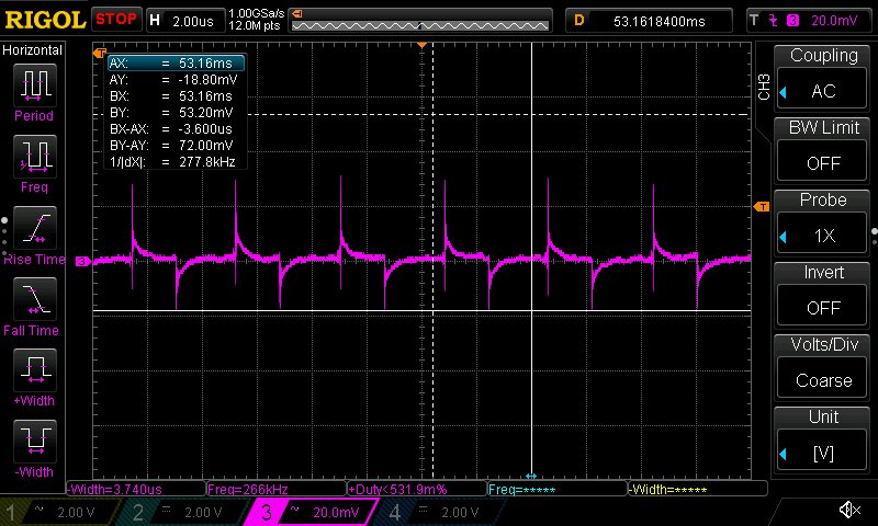
    Another thing I thought of could be noise injecting into Rt. Check Rt and make sure there isn't any ripple on that pin.

    Can you share the schematic and layout as well? That will give me a more complete picture of your system.

    Thanks,
    -Sam
  • Sam,

    Thank you for your active participation in solving this problem.

    I don't sure that pdf and rar will correctly upload to forum, so i give links to upload these files:

    There was not diode VD2 in original version of this pcb. In these files I put it in about the position in which it is now soldered on the board. Without it high-side mosfet broke at Current Load=2A; Vin > 20V.

    Scheme: https://yadi.sk/i/n_vMb7YI3aGSTu 

    PCB top: https://yadi.sk/i/bi6b8vvK3aGUW3  

    PCB bot: https://yadi.sk/i/7yLDyYhx3aGUWV   

    gerbers: https://yadi.sk/d/jpwujzeI3aGUXH 

    Waveform at Ron pin

  • Egor,

    Thanks for sharing that info. I'll take a look at it tonight.

    Was your Ron measurement taken with tip-and-barrel method at the pin of the IC? That amount of noise may affect the frequency and I want to make sure this is real noise on the pin.

    -Sam
  • Sam,

    I used another method when instead of a long ground wire a short grounded coil placed at the end of the barrel of the probe.
  • Egor,

    Okay thanks for measuring that with the proper method. Thank you for all the thorough information you're giving me. It's very helpful in this debug. This is a particular problem and it's very useful to have complete and organized data.

    The Ron waveform is still getting to me. This should be similar to the VIN triangular waveform but instead it looks something related to a square wave. What's the DC voltage on Ron?

    I see you have a single cap on the output with 200 mOhms ESR. This will create more ripple than is necessary for this controller to work and may confuse the feedback and cause it to trip earlier (unlikely but it's a possibility). You can try adding 1uF or 10uF ceramic in parallel with this cap.

    I'll keep thinking on this. I'm going to try to reproduce this in the lab on the EVM and I'll get back to you.

    -Sam
  • Sam,

    Thanks for your reply.

    There are DC waveforms of voltage on Ron pin of controller (without ceramic cap). DC voltage at Ron pin Vron=0.832...0.840 V

    I tested controller with ceramic capacitor. Adding it resolved promlem in instability at Vin>20V; Load Current = 2A; Ron=220kOhm(260kHz), but it didn't effect at switching frequency (it was still 260kHz). There is AC waveform at Ron pin with ceramic cap GRM31CR61H106MA12L (10uF) below.

  • Egor,

    Okay I have some good news for you and some bad news for me. I've recreated your conditions on our EVM and we're seeing the same switching frequency discrepancy that you're seeing. We set Ron=300k (calculated 150kHz) and saw 190kHz (you saw 200kHz). We removed some capacitance and saw 200kHz just like your board.

    So I believe we're dealing with an equation that doesn't align perfectly with reality. This is good for you because the frequency is very consistent (between your IC on your board and our IC on our board). This is bad for me because I get to go in and revise that equation.

    Thank you for your support in the debug of what appears to be an issue with our datasheet. We appreciate your engineering support :)

    I will close this thread for now. Let me know if you have any further questions.

    Thanks again,
    -Sam
  • Sam,
    Thanks for the help in the decision of the given problem.
    I wish you good luck in your work.
    It is hoped that the documentation will soon be corrected.