This thread has been locked.

If you have a related question, please click the "Ask a related question" button in the top right corner. The newly created question will be automatically linked to this question.

BQ34Z100EVM: BQ34Z100-G1 EVM no acknowledgement after golden image

Part Number: BQ34Z100EVM
Other Parts Discussed in Thread: BQSTUDIO,

Hello,

I'm currently working with the BQ34Z100EVM, EV2300 and the latest BqStudio version (1.3.86.3).

I followed the user guide step by step:

1. I programmed the device to the latest version of firmware and pressed execute FW

2. set the number of serie cells (in my case 10)

3. set the VOLSEL to 1 and press reset

4. calibrated volatge, temperature, CC Offset and Board Offset, Current

5. updated the correct Chemistry (SDI INR18650 - 29E, Chemistry ID 2019)

6. created new .srec file with golden image

6.1 during the creation of the new .srec file an error message displayed: "ROM command result return invalid checksum"

6.2 but after the creation of the .srec file BqStudio displayed that the creation was successful and the error message was gone so I thought that should be fine

6.3 I programmed the device with the created .srec file and pressed execute FW

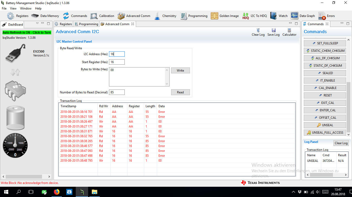
After a few seconds the connection to the device got lost and there is no acknowledgment at all. I'm also not able to programm the default Firmware

to the device again.

I guess the golden Image is corrupet but I have no idea why. Before I will order a new device I want to know what the problem was and how I can solve it.

  • Hi user5769503,

    Please probe the TS pin with a scope to determine if a pulse is seen. If pulse is seen, the firmware is executing. If the pulse is not seen, the gauge may be in ROM mode or possibly bricked.

    Attempt communication with the device at address 0xAA, if no response occurs, attempt to communicate with the device at address 0x16. If the device responds on 0x16, reprogram the device with the SREC available from the firmware on the device page.

    Sincerely,
    Bryan Kahler
  • Thanks for the quick reply. There is no pulse at the TS pin. How can I disable ROM mode or bricked mode?

    I tried the communication as well but no answer.

  • Hi User5769503,

    Please include a log of the attempted transaction from both a logic analyzer and analog scope to look for signs of life.

    After setting the device to VOLTSEL = 1:

    1. What was the voltage used to power the device
    2. Which external divider (if any) was utilized

    Voltsel being set to 1 will disable the internal divider. If the external divider is not connected to limit the voltage into the bat pin, it is possible that the device was taken beyond maximum survivable limits.

    IF this is the case, please order another board, or order some samples and reflow a new device on the EVM.

    Sincerely,
    Bryan Kahler
  • I connected to board normaly and measured with a scope for a pulse at the TS pin, but there was none.
    After I set VOLTSEL = , the voltage to power the device was 39,11 V. As an external divider, I placed both the jumper to > 5 V (J5) and one on 48 V (J2) but nothing else.
    The device didnt broke after I changed VOLTSEL = 1, it broke when I programmed the golden image to the board.
    How can I disable ROM mode or bricked mode?
  • Hi User5769503,

    Measure the voltage at the BAT pin as well as the REGIN pin. If these voltages are below minimum voltage defined in the device datasheet, the device will not function.

    Once the device is sufficiently powered (up to 1 V on BAT pin, but not greater with VOLTSEL=1), REGIN, and 2.5V output from REG25, probe the TS pin again. If the TS pin is now pulsing, attempt to communicate with the device at address 0xAA. If the TS pin is not pulsing, attempt to communicate with the device at address 0x16.

    If the device is powered and communication fails, please include a log of the attempted I2C transactions from both a logic analyzer and analog scope of the I2C lines.

    Sincerely,
    Bryan Kahler
  • Hi Bryan,

    I measured the voltage at BAT pin as well as the REGIN pin and the voltage was below the minimum voltage in the datasheet....

    so my device will not work. I still don't know what my mistake was. The external divider was connected after setting VOLTSEL = 1.

    Could it be that I used a incorrect bqz file?

    0601.bqz.rar

    At the beginning I used the bqz file which was installed by default from bqstudio, its titeld wrong-0100_0_16-bq34z100G1 in the zip file becauce with this bqz file I was not able to calibrate the device.

    After some research I found a bqz file which worked (0100_0_16-bq34z100G1) and I used it before/during the device broke.

    Could that cause the problem?

  • Hi User5769503,

    If the voltage at the REGIN pin is below the minimum voltage in the datasheet, the device is not powered.

    The 0100_0_16-bq34z100G1.bqz that comes with the latest version of bqStudio is the proper bqz for the device.

    Please provide a schematic showing component values, source voltage, voltage levels on the rails for the device and what the measured voltage at the pins are.

    Sincerely,
    Bryan Kahler