This thread has been locked.

If you have a related question, please click the "Ask a related question" button in the top right corner. The newly created question will be automatically linked to this question.

UCC28780: UCC28780 ABM unstability

Part Number: UCC28780

Hi,

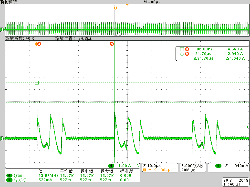
This design use the secondary resonance with GaN-FET: the primary clamp capacitor is 1uF/ceramic; the secondary resonant capacitor is 33uF/25V.

The test condition is: Vin=390Vdc, Vout=9Vdc, Iout=1.2A.

I found the second resonant current is different with the first resonant current.

Why there is this abnormal phenominon? How to resolve it?

BR

Eleven Chen

  • Dear Eleven,

    Thanks for interested in TI's solution.
    I want to make sure you use 390Vdc as input voltage, or you use AC input and get the 390Vdc after the bridge?
    The reason I want to make sure your input voltage is because the ripple on the input cap may cause the resonant current like this.
    Also, can you provide the resonant current with more pulse?
    Maybe 5-8 pulses will be good enough.

    Best Rerards
    Kevin
  • Hi Kevin,
    Thanks for your reply.
    There is PFC stage at the front-end.
    Now I use the seperated DC source to debug the ACF stage.
    I have tried to check more pulses, but it still shows the same abnormal issue.
    This issue will cause the SR driver turn off prematurelly. Also the primary current RMS is higher.
    Please help advice.
    Thanks.

    BR
    Eleven Chen
  • Dear Eleven,

    Thanks for your input.

    Are you also using secondary resonance?

    If so, you can reduce Ldamp to have stronger damping.

    Stronger damping will have more stable Vco1, which will mitigate the SR turn off prematurely.

    Can you capture the Vgs(SR), Vco1, Ipri at the same time?

    It will give me more information on the issue.

    Best Regards

    Kevin

  • Hi Kevin,
    Thanks for your reply.
    When I capture the Vgs(SR), Vco1, Ipri at the same time, the primary high-side GaN-FET was damaged.
    I don't know what happened.
    Could you help give some advice?

    Besides, I have put the Rcomp and N-MOSFET at FB pin.
    I found this circuit is very useful.
    And now, I put 390Kohm as the Rcomp.
    I am not sure what is the minimum value Rcomp I can use?
    If I use smaller value resistor, what will happen?

    Thanks!


    BR
    Eleven Chen
  • Dear Eleven,

    Sorry to hear your hide side GaN was damaged.

    Do you try it again carefully?

    Do you also capture primary side waveform at the same time?

    Because the primary side ground and secondary side ground is different.

    You mentioned Rcomp is useful. Do you mean more stable ABM mode?

    Basically, we won't suggest lower than 500kohm.

    Because too small Rcomp will affect startup and OPP.

    Smaller Rcomp will cause smaller Vcst and Ipeak.

    Best Regards

    Kevin

  • Hi Kevin,
    Why Rcomp has influence to startup/OPP?
    Could you help explain?
    Thanks!

    BR
    Eleven Chen
  • Dear Eleven,

    Smaller Rcomp will cause higher Icomp and higher Ifb.

    So the maximum peak current on CS pin will be smaller(negative feedback Ifb).

    During full load startup, if Rcomp is too small may cause the issue.

    Also, OPP point will be too small.

    Best Regards

    Kevin