This thread has been locked.

If you have a related question, please click the "Ask a related question" button in the top right corner. The newly created question will be automatically linked to this question.

TPS56121: TPS56121. Sometimes does not switch on.

Part Number: TPS56121

Hi guys

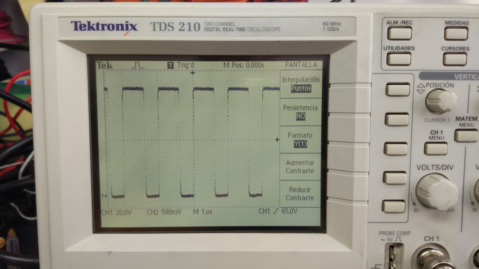
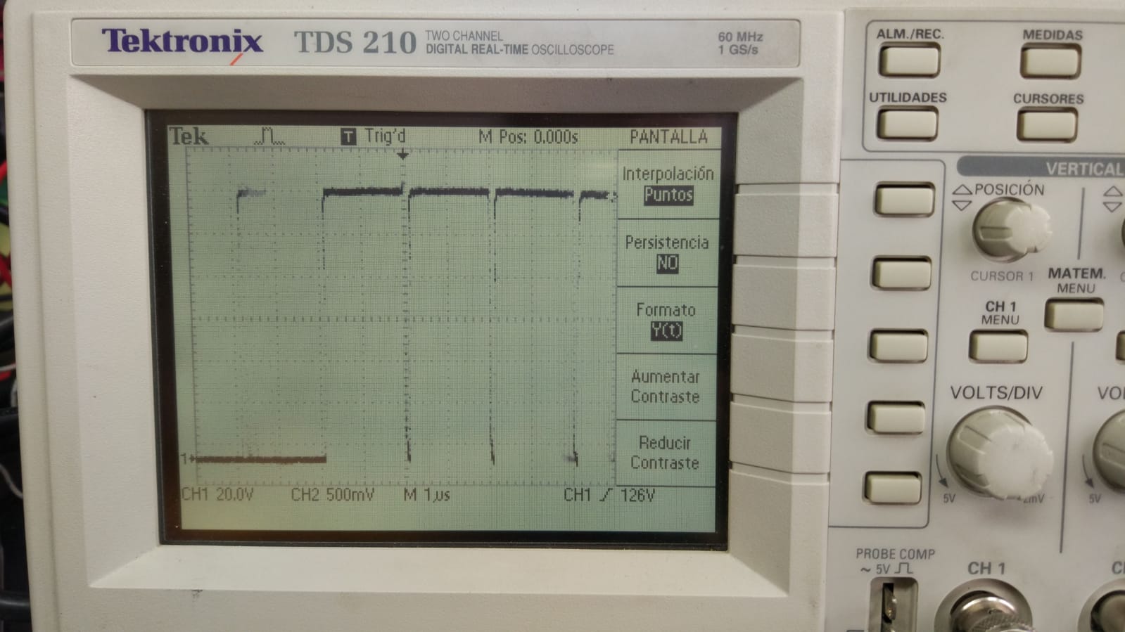
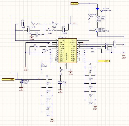
I used the TPS56121 to convert an input of 10.5-12.6V to 7.4 v with a maximum output of 6 A.

There are 15 of these design together in the same PCB, separated for every output I need.

Actually, they perfom very well when they are already on and them put any kind of load (pure resistive as a power resistor or pure inductive as a car bulb), but if I try to power them on while the load is already connected, they fail.

As the finally of the project is power servo outputs, when I put a servo as a load, they works fine, switch on correctly and work correctly whatever the amperage required.

Sometimes they do not switch on without load.

Here is what is happening to me and I write  to you because I am not able to figure out what is wrong and why.

Hope you can explain me something. Here you can find the schematic.

thank you for all.

Jose Angel.

  • Hello,
    How would you control or implement the EN/SS pin? There is a 10uA coming out that pin to charge capacitor for the soft-start timing.
    When you power up the circuit with the load attached to the output, the input side has to charge the output capacitance and the load. If the soft-start time is so short, the charge will be much higher or in-rush current much higher. Can you connect a capacitor from EN/SS to ground and re-try? Please see page 12 of datasheet for more details (try 3.3nF to 10nF).
    Kit
  • Kit Nguyen said:
    Hello,
    How would you control or implement the EN/SS pin? There is a 10uA coming out that pin to charge capacitor for the soft-start timing.
    When you power up the circuit with the load attached to the output, the input side has to charge the output capacitance and the load. If the soft-start time is so short, the charge will be much higher or in-rush current much higher. Can you connect a capacitor from EN/SS to ground and re-try? Please see page 12 of datasheet for more details (try 3.3nF to 10nF).
    Kit

    Hi Kit, Thank you for your reply.

    I did that few days ago, with 1nF capacitors and 100nF capacitors. The difference, as you say, is the delay in switchng the converter on, but when I attach the load (power resitance) still happen the same.

    I am thinking about the type of load, if it is pure resistive as a power resistance, then, we get a high initial current, maybe that is the problem.

    Also I tought about the fact that there are 15 of those converters together, could be a noise problem between each other?

    Thank you for your help.

    Jose Angel.

  • Hello Jose,

    Can you please share the picture of your load connection to those rails? If I understand your statement correctly, you have 15 rails output and connected to the same one load, right? If yes, are those rails have same output voltage or different output voltage? And, can you separate the load to each rail?

    Kit

  • Hi Kit,

    Every output has one different load.

    I just tried to connect each servo to each output and worked fine with the bench power supply but when I tried to use the batteries, it did not work. Some converters worked and some do not.

    I am not able to figure out what is happening and why it is doing that.

    I have a smaller prototype board litellary equal to this one but just two outputs, and works fine in every situation.


    This thing is making me crazy.

    Thank you.
  • Hi Jose,
    From your description, it seems to me the batteries do not have enough charge to deliver during the soft-start. Can you limit to 5 rails instead of 15 rails at the same time? I could not see the picture of your setup. Any waveform will help to understand better too.
  • Hi kit, thank for you help.

    The battery can delivery 150 A continuous, so, it should not be a problem.

    I have two exact prototypes with 2 outputs each one, and one big with 15.

    I moved to the littles ones because the prototype 1 works fine, so i used it to compare.

    The first prototype works very well, here you have the switching output:

    I see a very stable output, no load. Same duty cycle. Switching frequency of 500khzThe Pgood signal is stable and do not overheat. 

    Now, the second prototype, with componentes removed from the big PCB in order to test them alone. Must say they are the same batch of components, and the switching output look like this:

    As you can see, the output its not a perfect square signal as the first was. No constant duty cycle. And variable switching frequency.

    I hope this info can help us to find out the issue.

    Thanks for all, Kit.

  • Hi Jose,

    First, I assumed that the switch node (pin 6 to 11) signal is on those waveform. If yes, the CH1 of waveform has 20V per division. Is your probe set to 10X or the input voltage is much higher than 14V.  The maximum input voltage for this device is 14V. Sorry, I could NOT see CH2 signal.

    On the bottom waveform, the switch node looks to have the maximum duty cycle (page 5 of datasheet, 90%). Can you check your output voltage, load step at right before the third division such that the duty cycle increases to maximum D?

    Do you have any support from local Ti FAEs or sale engineers in your region? can you please share the picture of your board setup?

    Kit

  • Hi Kit.

    Sorry about that, but I do not remember the settings of the osciloscope, but I remember in measures section to see 12 V peak of the square signal, which I suppuse is correct due to the 12.6 input votlage.

    Last week I made different test on the littles boards and they worked properly. I tried to puts three of those board in parallel and the issues with the switch on start again... I am still not able to figure out what is making this issue...

    Does it any sense for you, Kit?

    Thank for your time.

    jose Angel.

  • Hi Jose,

    Since the part works properly in single PCB layout, so the design is good.  When you put all 3 rails together on the same PCB layout, the issue started. So, it must related to the PCB design or test setup. Can you share the PCB layout or picture of setup (how did you connect to the load)? As I recalled the second waveform, the duty cycle was increased to the maximum. Did you have any load transient? 

    It sounds to me the test setup or PCB related.

    Kit