This thread has been locked.

If you have a related question, please click the "Ask a related question" button in the top right corner. The newly created question will be automatically linked to this question.

the output problem of TPS63001

Other Parts Discussed in Thread: TPS63001

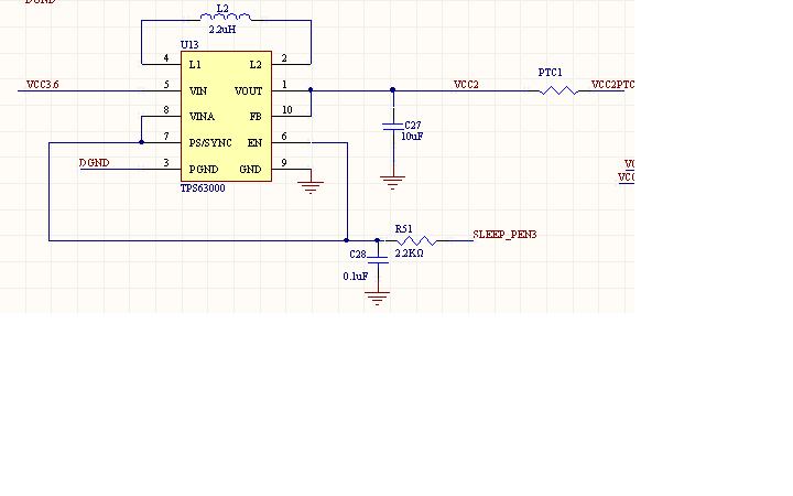
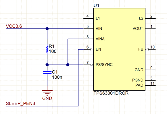
We want to use TPS63001 for testing. We want to control whether it is powered by the EN pin. Now let's talk about the test. Please explain why.

when the pin of the processor passes the 100 ohm or 2.2k resistor to the PEN3, the TPS63001 can output 3.3v voltage normally,but after about 2 minutes, the chip will be hot, and no circuit is connected after the power chip. When the pin is connected to a 10k resistor, the output is 4.5v.

  • Hello liufeng28,

    To control the output, use the EN pin separately from VINA and PS/SYNC.

    Furthermore, if you want to enable power-save mode, connect PS/SYNC to GND.

    Also, please take a look at the recommended layout in the datasheet, and follow the guidelines. Your ground lines are too thin, and I do not see an input filter capacitor placed close to the TPS63001. Could you also tell me the part number for L2?

    Best regards,
    Milos

  • the cause of the problem was found ,because the temperature of the blow gun exceeded 400 degrees when welding.
    the L2 is 2.2uh inductance.

    but there is a problem,always when the sleep_pen3 is the 3.3v,the output of the tps63001 will be 3.3,but some time(very few times,20 times maybe once.) the output of the tps63001 will be 4.5v,I don't know the reason for this phenomenon.
  • This phenomenon is when the power is on, when the control pin sleep_pen3 is 3.3v, sometimes the output of the tps63001 will be 4.5v.
  • i have two tps63001 chips in my board,so as to save place,the two tps63001 chips Share a input filter capacitor. the input filter capacitor near the two tps63001 chips.
  • Hi liufeng28,

    Did you connect the TPS63001 as I indicated in my previous post? It is not properly connected if it is still the same as in your first post. VINA is the supply pin for internal control, and should be connected via 100 Ohm resistor to VIN pin.

    Could you tell me the exact manufacturer part number for L2, and what is the required output current in your design?

    Best regards,
    Milos
  • thanks a lot,Our design has been made, and no one has responded to me in your power management forum in the early stage.

    so next time I will do it according to your previous post.the L2 is 2.2uh inductance and the required output current is 900mA.
  • Hi liufeng28,

    I am sorry to hear that no one responded to you during the early stage design, that should not happen normally.

    It is recommended to have a capacitor as close as possible to the input and output of each switching regulator in your circuit, otherwise you may experience problems such as excessive ringing, increased ripple or EMI issues. As for the inductor, I was asking because it seemed to be small for the required current and inductance. Please check the current rating and if the DC resistance is not to high. Otherwise, you can see the recommended inductors in the datasheet and in the WEBENCH.

    Best regards,
    Milos

  • thanks,how to find the WEBENCH?
  • Hi liufeng28,

    You can start WEBENCH on the TPS63001 product page, on the right side of the window. Fill in the design specifications and clik "Open Design".

    Or you can start from scratch and go directly to WEBENCH:
    webench.ti.com/.../

    Best regards,
    Milos