This thread has been locked.

If you have a related question, please click the "Ask a related question" button in the top right corner. The newly created question will be automatically linked to this question.

LM4041A12: Resistor Values

Part Number: LM4041A12
Other Parts Discussed in Thread: LM4040-N, TL431


There is concern here that the equations or resistor placement for the adjustable LM4041 are incorrect. The TI spec shows something similar to what’s below.


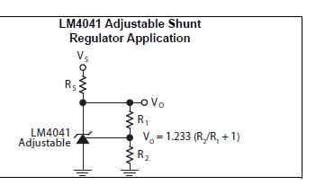
If R2 approaches infinity then Vo approaches infinity, per the equation. Seemingly, as R2 approaches infinity Vo should approach the diode reverse voltage value, approximately 1.24V.


Please clarify.

  • Hi Laura,

    Thank you for bringing this to our attention. For the LM4041 the FB input gate is a PNP instead of a NPN like on TL431 devices. Due to this the R2 and R1 values are flipped on the equation. Pg 12 on the datasheet for LM4040-N goes over a little bit more detail.

    On a TL431 the FB pin is always 2.495V relative to the anode. In the LM4041 the FB pin is 1.233V relative to the cathode.


    -Marcoo