This thread has been locked.

If you have a related question, please click the "Ask a related question" button in the top right corner. The newly created question will be automatically linked to this question.

BQ500511A: Snubber design

Part Number: BQ500511A
Other Parts Discussed in Thread: BQ50002A

Hi,

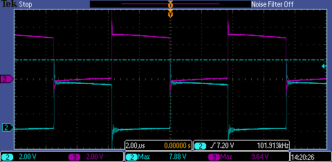
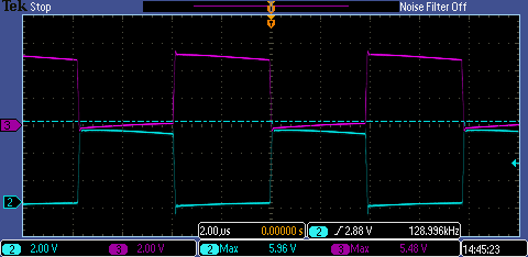
We made a custom charger which is almost a complete copy of the bq500511A application schematic from the datasheet. We only changed the coil to match the RX coil we are using. The new TX coil is the WT151512 from TDK. We experience some issues with the device heating up considerably which causes the charging to stop after some time due to the automatic turn off with the NTC becoming too hot. We did some resonance measurements on both our own, custom charger (with the bq500511A) and the bq500212AEVM board. These resulted in following graph:

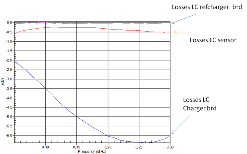
The curves on top show almost no loss, which is what we expect. The refcharger is the bq500212AEVM board, the sensor is our TX and the charger brd is our own custom charger (copy of bq500511A application schematic). With our charger, there is a clear loss which is already -3.5dBm at 100kHz. We noticed that when we removed the snubbers, the curve was almost exactly as the curve from the refcharger.

As the only thing we changed is the TX coil, should the snubber parameters also be adapted to the new coil?

Why are there snubber circuits used? The bq500212AEVM does not use these.

Could this loss have something to do with our device heating up? When I removed the snubbers, I did not see significant decrease in heating up, but maybe the snubbers can help when they are retuned?

Best regards,

Wout

  • The snubber network on the bq50002A/511A design will control voltage spike on SW1 & SW2 switching nodes. If the network is burning excessive power I recommend looking at re-tuning. Key thing to look at is the voltage spike on the two switch nodes, need to remain below 7V.

    Also some things you may have already checked:
    1.) The resonant caps in series with Coil should all be low loss COG or NPO types.
    2.) Is the loss and thermal rise at high loads, possibly core saturation. As a test add a 2ed ferrite from another core, this would reduce risk of saturation.
    3.) Test with TDK WT202012-15F or WT303012-12F2, I have used them before with good results.
  • Hi Bill,

    I see what you mean with the snubbers and the voltage spikes:

    Without snubbers

    With snubbers

    The resonant caps are C0G type and we don't really need a high load. In worst case scenario, we need a 60mA charging current for the battery. I don't suppose this is considered 'high load'. I have done some tests with the WT202012-15F as well. The voltage at the switching nodes was about the same but the input current was higher. We also made tools to make sure the coils are perfectly aligned after assembly, the next step is trying to minimize the material between the coils (this is now 2x0.7mm for the casing of the charger and the sensor). I noticed that this has already a great effect, at least on the input current. Hopefully this will be enough to control the heating.

    Best regards,

    Wout

  • Thanks for the update.
    The snubber can be reduced, larger R or smaller C the spike will increase but good enough for your application.
  • Hi Bill,

    Is it possible that this has something to do with the device heating up, or should this not have much impact?

    Best regards,
    Wout
  • The snubbed would add a load to the bq50002A and increase thermal rise. Hard to say if this is the only cause of device heating up that you are seeing.
  • I will try to see if it has a positive impact to reduce the snubbers. Thanks for the information.

    Best regards,
    Wout