This thread has been locked.

If you have a related question, please click the "Ask a related question" button in the top right corner. The newly created question will be automatically linked to this question.

TPSM846C24EVM-006: How to hook up network analyzer

Part Number: TPSM846C24EVM-006
Other Parts Discussed in Thread: TPSM846C24

Team,

My customer has the EVM and has the following question:

The eval board for the TPSM846C24 has connections to sweep the control loop using a BODE 100.


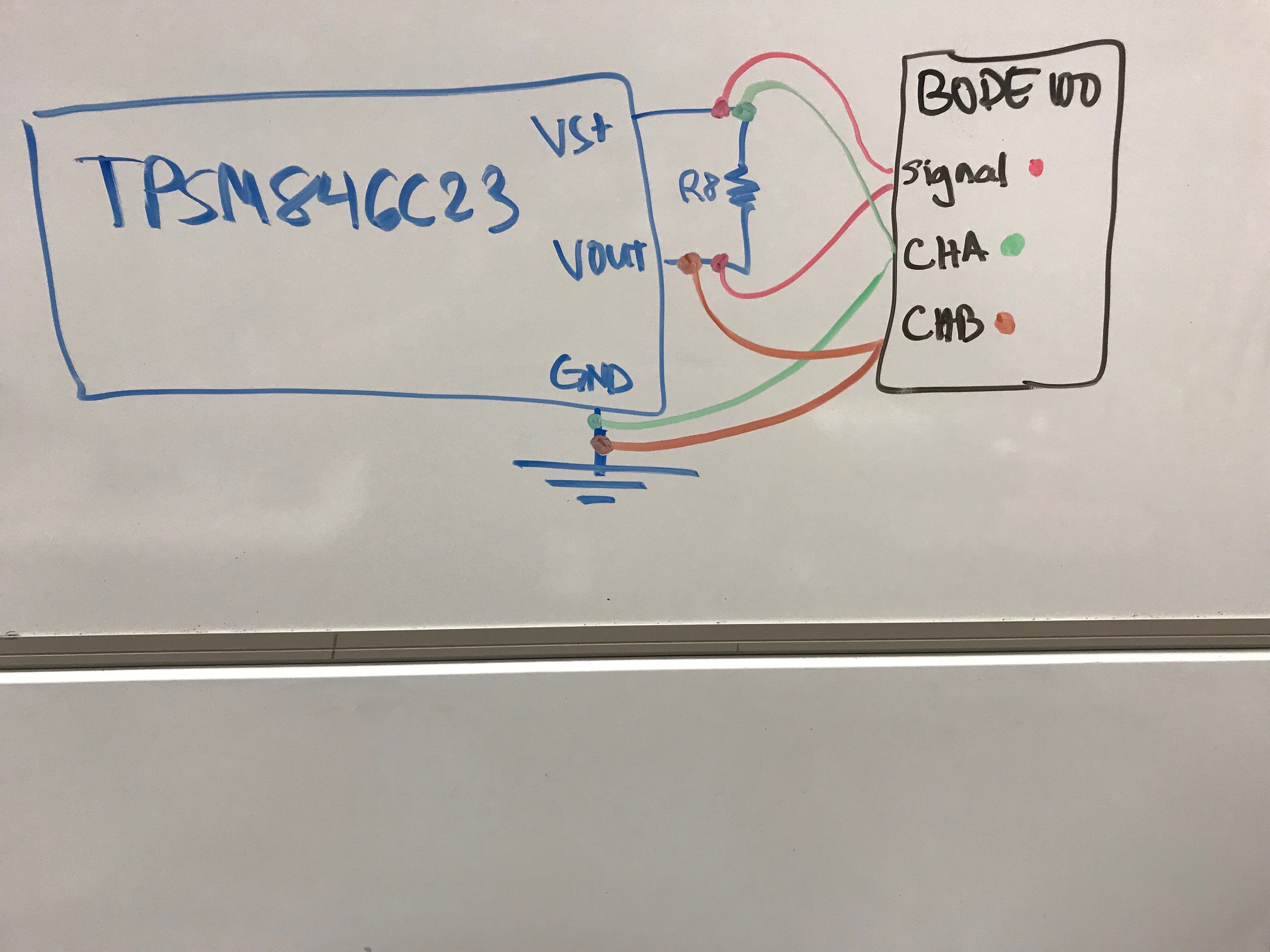
Question….in the past, every power supply I’ve swept the control loop on, had the BODE 100 injection transformer connected across the injection resistor and the  scope probes to the BODE 100 attached to the on either side of this resistor and the ground clips on the scope probes attached to the PGND.

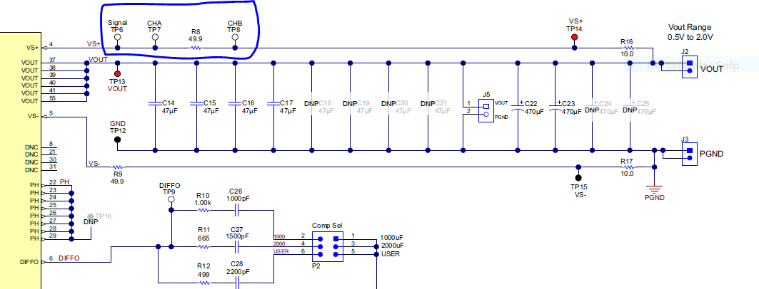
How should I hook up the BODE 100?   Should I hook up the scope ground leads to PGND or the Signal , TP6 test post?  If I hook up the scope ground clips from both scope probes  to TP6, the scope probe connected to TP7 ( CHA ) is shorted out and won’t get any signal.

The eval board pin descriptions state this….


 Can you explain this? 

Thanks,

Brian 

  • Hi Brian,

    You are correct in that you would have an injection resistor and place the probes on each termination of that resistor. The description you attached for Signal mentions that to inject the signal, the clips should be placed between Signal and CHB. CHA and CHB probe ground should never be connected to CHB since that would short the signal and you would not see anything on the bode plot analysis as you've mentioned. What you would do in this case is connect the signal injection point between Signal TP and CHB TP. For the probes, you would connect the first one to CHA and GND and the second one between CHB and GND.

    Hope this clears up the misunderstanding.

    Regards,

    Jimmy