This thread has been locked.

If you have a related question, please click the "Ask a related question" button in the top right corner. The newly created question will be automatically linked to this question.

UCC28951-Q1: Configuration of ADEL pin.

Part Number: UCC28951-Q1
Other Parts Discussed in Thread: UCC28950

Hello Sir,

The voltage given to the voltage divider circuit for adaptive delays ADELEF pin and ADEL pin is either from Vref or CS ?

whether we have to take it from Vref or CS ?

In fig no.55 , resistor  R26 is between the CS and Vref.

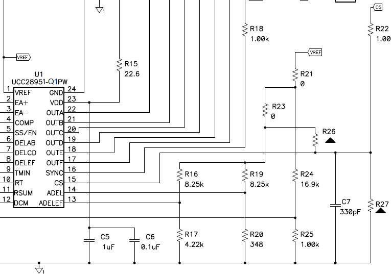
What is the value of that resistor and its use ?

  • Hello Rajashekar

    The UCC28950 can modify the baseline delays set by the resistors at the DELAB, DELCD and DELEF pins according to the voltage at the ADEL and ADELEF pins. If the ADEL or ADELEF pins are connected to the CS pin through a potential divider then the delays become a function of the voltage at the CS pin and therefore a function of the primary side current. These delays and how they are set up and controlled are described in sections 7.3.6 and 7.3.7 of the UCC28950 datasheet.

    The designer of the circuit above wanted to show some of the added flexibility in the use of the ADEL and ADELEF pins. The baseline (unmodified) delays are set by the resistors at the DELAB, DELCD and DELEF pins. The usual adaptive delays described in the datasheet are then set up by populating R17, R16, R26, R20, R19 and leaving R23 open circuit (R26 = 0 Ohm). This connects the ADEL and ADELEF pins to CS through the potential divider.

    If R26 is left open circuit and R23 populated with a zero ohm link, then ADEL and ADELEF are connected to VREF. The voltage at the ADEL and ADELEF pins is a fixed proportion of VREF so it's no longer a function of the load current. However, the voltage at the ADEL and ADELEF pins modifies the baseline delays set by the resistors at DELAB, DELCD and DELEF.

    There is no particular reason why one approach is better than the other. It depends heavily on the characteristic of the power stage being controlled. Most designers choose to use the Adaptive Delay function as it is shown in the data sheet - or with R26 = 0R and R23 open circuit.

    Regards
    Colin