This thread has been locked.

If you have a related question, please click the "Ask a related question" button in the top right corner. The newly created question will be automatically linked to this question.

TPS65218: PMIC shutdowns randomly Rev B1.

Part Number: TPS65218

Dear Friends,

We had used TPS65218 B1 in our custom board.

The issue I faced is PMIC shutdowns (All rails off) randomly. 

Please guide me how can I debug and find the actual reason behind shutdown.

I had verified that current of each rails are well below limits.
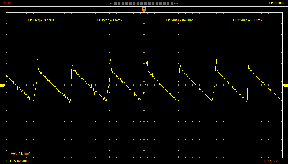
Vin is +5V

Can you please send me the PCN of revision D0.

I had unmasked the all interupts using I2C. Now on INTA pin I'm getting the pulse when there is an event generated by PMIC like PB pressed or any fault arises.

Now I want to read the PMIC status register and print on console when any event interupt arises.So that I knows which event was generated before shutdown.

Any one had done this before or guide me how can I do this.

Thanks

Chetan

  • Chetan,

    You are definitely getting a fault on one of the DC-DC rails or the LDO.

    The overvoltage and undervoltage tolerances of the TPS65218 are very tight. If you are using TPS65218 B1 silicon, then DCDC4 is more likely to be causing the issue.

    The only way to debug this is to monitor the voltage rails with an oscilloscope during the power-up sequence and determine which DCDCx rail (or LDO1) causes PGOOD to go low. You need to trigger the scope to catch the falling edge of PGOOD and measure the ripple voltage to verify which DCDCx rail is out of tolerance. To get the ripple measurement in view, you can use DC coupling, set the offset of the probe channel equal to the DCDCx output voltage, and set the vertical scale to 20mV/div. Then you can set the cursors of the scope at the high (OV) and low (UV, or PG) limit of the DCDCx rail. For example, DCDC1 = 1.1V +/- 3%

    Generally speaking, adding more capacitance to the rail will smooth out the output voltage (reduce ripple), and DCDC1-4 can operate up to a max of 100uF at the output of the converter.
  • Thanks Brian for quick response.

    Here I have attached the scope of the DCDC4 as suggested....

    47uF capacitor was already there and I had added another 47uF in parallal.

    Additionally I had connected 220pF capacitor on L4A to ground (Ceramic - Non SMD).

    But There is not significant difference in the ripple.

    The Inductor I had connected is 2.2uH.

    What Can I do next to improve it further ?

    Apart from that please send me the changes in Revision history of B1 to D0 revision.

    Thanks

    Chetan

  • Hello brian

    I forgot to mention that the attached waveform is of DCDC3 and scope is in AC coupling mode...

    Thanks
    Chetan
  • Hello Brian,

    e2e.ti.com/.../2466468

    In above thread the resolution of the issue is reducing the capacitor at DCDC4 output.

    Could you please confirm the solution.


    Thanks
    Chetan
  • Chetan,

    The link you have provided is related to too much capacitance on DCDC4. If you are worried there is too much capacitance on DCDC4, then the (47uF) bulk cap at the output should be removed. I can confirm this is the correct way to fix issues related to too much capacitance.

    There are other workarounds for DCDC4 out of tolerance that are only required for TPS65218 -B1 silicon.

    If you order samples of TPS65218D0 and test in your system, you will not need any workarounds. The majority of issues on DCDC4 were related to the -B1 silicon and were resolved in -D0 silicon. This is the primary reason -D0 was released and -B1 is now marked as NRND.

    However, even on -D0 silicon, the maximum output capacitance is not changed and is still 100uF. Testing -D0 silicon will reduce the number of variable in this question, though, and it is advisable to switch as soon as possible.


    Thanks,
    Brian