This thread has been locked.

If you have a related question, please click the "Ask a related question" button in the top right corner. The newly created question will be automatically linked to this question.

UCC28070: disable one phase at light load

Part Number: UCC28070

Hello:

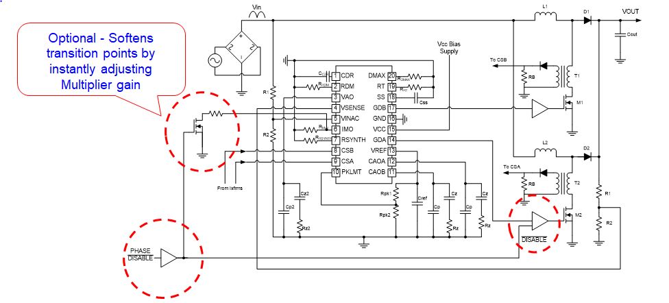
our customer has light load efficiency requirement. We have to turn off one phase at 10% load.  In order to have " soft" enable one phase feature, we designed below circuit to turn on/off one of the phases.

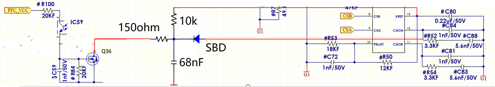
IC59 is the photo coupler which will tranfer secondary light load detection signal to primary side.

During turn off: Q36 will be pulled low and CAOA will be pulled low by the SBD. Here we use schottky is because it has lower voltage drop than signal diode.

During turn on: 68nf cap will be charged by Vref via 10k resistor. And the CAOA will be clamped to 68nf cap voltage via SBD. So the voltage of CAOA is slowly rise up. In normal condition, CAOA is less than Vref. So SBD blocked CAOA to 68nf cap. This circuit will not impact PFC control loop in normal condition.

in that way, we can have soft start feature when two phase are enabled.

since it is a new circuit, our customer wants us to confirm it with TI FAE to avoid any side effect of this circuit.

please help to give your comment about that.

Thanks

Tao Wu 

  • Hello Tao Wu,

    In your circuit you are pulling the current amplifier output close to ground for channel A.

    This may not fully turn off channel A because of the voltage drop in the SDB diode, 150 Ohm resistor and noise pickup in the pcb trace.

    It is probably easier to directly turn off the GDA gate drive as in the sketch shown below:

    Switching from  dual phase operation to single phase operation will cause a disturbance in the control loop.
    The pulse width for GDB will need to increase in order to compensate for the loss of the GDA signal.
    The sketch shows a change to the multiplier resistor that effectively speeds up the control loop and bypasses to slow voltage feedback of the pfc.

    Also you will need to have some hysteresis on your input signal as you switch from interleaved to single phase and back again.
    I recommend that you thoroughly test your circuit under all operating conditions of line and load both static and dynamic
    Also measure your efficiency with the modified circuit and unmodified circuit and check for any improvement.

    Regards

    John 

  • Thanks for your quick response. But I still have couple of question may need your help.

    1, Coule you please provide the low voltage threshold of CAoa/b which will disable the drive?

    2, based on your proposal, the IMO will be reduced by parralling resistor on when two phases in operation? Is my understanding correct?

    3, I am afraid your proposal cannot solve our problem. Once one phase is disabled, no matter what IMO is set, the disabled phase will have maximum duty cycle, since the current signal is lost. So once the phase is enabled, it will drive PFC mosfet with maximum duty. The maximum duty we set as 87% for better harmonic purpose. in our orignal design, we simply disable one phase via ENA pin on driver IC.  sowe can see large input current spike. And If system is having dynamic load condition at that range, we will see EMI choke saturated and EMI fail.

    please check below waveform on our orignal design.

    ch1: one phase drive Ch2: CT(PFC mos current information) CH3: AC current.

    That is why we want to have soft start. the peak current happened at that the first pulses and limited by OCP feature of UC28070.  so I am afraid changing IMO may be helpful to reduce the duration but it cannot emlinate the current spikes on AC input.

    4,  Could you let us know if we do not change IMO, in which condition the disturbance may happen? we can double check that.

    Thanks

    Tao Wu

  • Hello Tao Wu,

    The CAO output is compared with the internal PWEM ramp. And unfortunately for your application, the ramp voltage levels are not tested as part of the electrical parameters in the data sheet. This makes your design idea problematic and is one of the reasons I recommended the above circuit which directly turns off the gate drive output as required at light load.
    When the pfc switches to single phase operation, you can expect the pulse width of the enabled gate drive to double. It will not go to maximum duty cycle.
    The intention of the circuit is to switch to single phase operation at light load only.
    Light load is detected and set by some external circuit that is not described in this E2E post.

    Regards

    John

  • This thread is being answered by email and so I am marking this post as closed.
    Regards
    John