


Hello Ti,
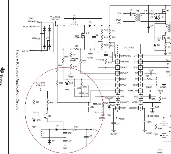
the circuit below is the design example which come from page 13 of UCC28500's datasheet.
Here is my question: How is the auxiliary power circuit work? The design of D5 & D7 is unlike the standard forward structure. My guess is when circuit start up, Vccbias will charge the C6 and C12+C20 to 15V. Then UCC28500 start working and charge C12 to 15V through L1 ( transformer) that will make C12 + C20 become 30V (15V+15V) and force Q5 turn off. Will C6 be charged to 30V, too? 30V Vcc will burn out the PWM IC?
Thank you .

