This thread has been locked.

If you have a related question, please click the "Ask a related question" button in the top right corner. The newly created question will be automatically linked to this question.

TPS65177: AVDD VGH power down and screen flicker

Part Number: TPS65177

Dear Team,

1.After measurement, the VGH voltage power down and the screen become black, and the duration of the screen flicker is consistent with the duration and frequency of voltage reduction, as shown in the figure.

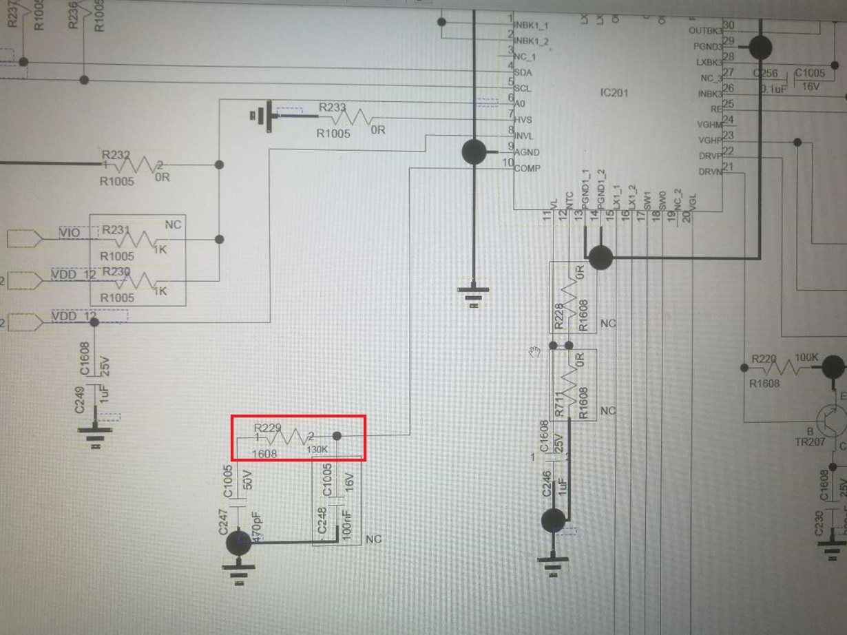
2. The circuit that appears to be flickering is different in classic design. The R229 is 130 ohms and the recommended to be 75 ohms. If we use 200 ohms, the screen flashes earlier, the frequency rate is higher, and the probability is higher.

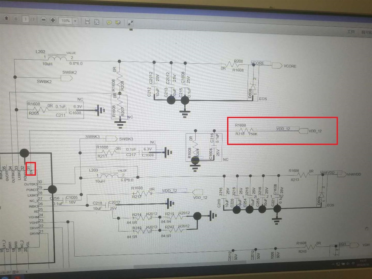
3. There is also a phenomenon that if a person touches the EN PIN of the chip with a dice, the screen flicker will pause.

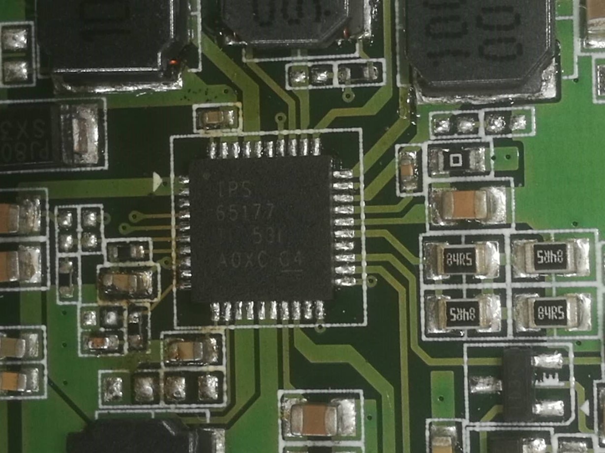
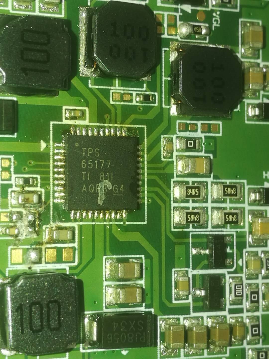
4. We only change the IC and other conditions remain unchanged, the TPS65177 TI 81 AQP8 G4 is ERROR, but the TPS65177 53 A0XC 04 is ok.

Thank you for your reply.

  • Hi Elsa,

    I have notified our expert regarding this topic. Please expect a response by 9/4/18.

    Thanks,
    Aaron
  • Hello Elsa,

    The drop in VGH supply is likely due to un-stability of AVDD boost converter. You mentioned that you are using a different compensation resistor then the one recommended in the datasheet. What is the reason for that? Can you please use 75K/470pf compensation network as recommended in the datasheet to see if improves the behavior? Also, high frequency noise filter capacitor C248 is recommended to be 22pf in the datasheet so I would suggest to use that value.
    Please let me know how these changes improve the issue.

    Kind Regards,
    Liaqat
  • Hi Liaqat,

    If we use 75kohm and 470pF compensation network,it maybe OK. But what's the root cause? Why the other IC work OK with  200kohm and 470pF  compensation network?

    Before the root cause we find out,all the suggestion is just a suggestion. we can change our design, and we will review it, but we need to know the root cause first.

    Best Regards,

    Elsa

  • Hello Elsa,
    I suspect boost feedback loop instability due to using incorrect compensation to be the root cause. One device may marginally work and another may fail if there is not enough phase/gain margin in the feedback loop. You can get a good idea of the loop stability by applying a load step and measuring the boost output voltage response. Higher level of ringing at boost output in response to a load step would indicate a lower stability margin and lower or no ringing at the output in response to a load step would mean a stable loop. You can do one stability measurement with the 75K/470pf combination as recommended in the datasheet and another with 200K/470pf that you are using to clearly see difference in ringing between the two cases.
    Kind Regards,
    Liaqat