This thread has been locked.

If you have a related question, please click the "Ask a related question" button in the top right corner. The newly created question will be automatically linked to this question.

BQ51013B:BQ51013B problems with overheating, low output and dropping output to 0.

Part Number: BQ51013B
Other Parts Discussed in Thread: BQ51013

Hello!

I'm using BQ51013B (VQFN) in my design. It connects fine with Qi-standart TX (it works fine with my phone). But there are some problems:

1) BQ51013B getting really hot after second.

2) Output of BQ51013B always under 4.3V (but it enough for LTC4054).

3) After 3 seconds output of BQ51013B drops back to 0, and there is no any end-transfer packets (Qi TX do not stop the energy transfer).

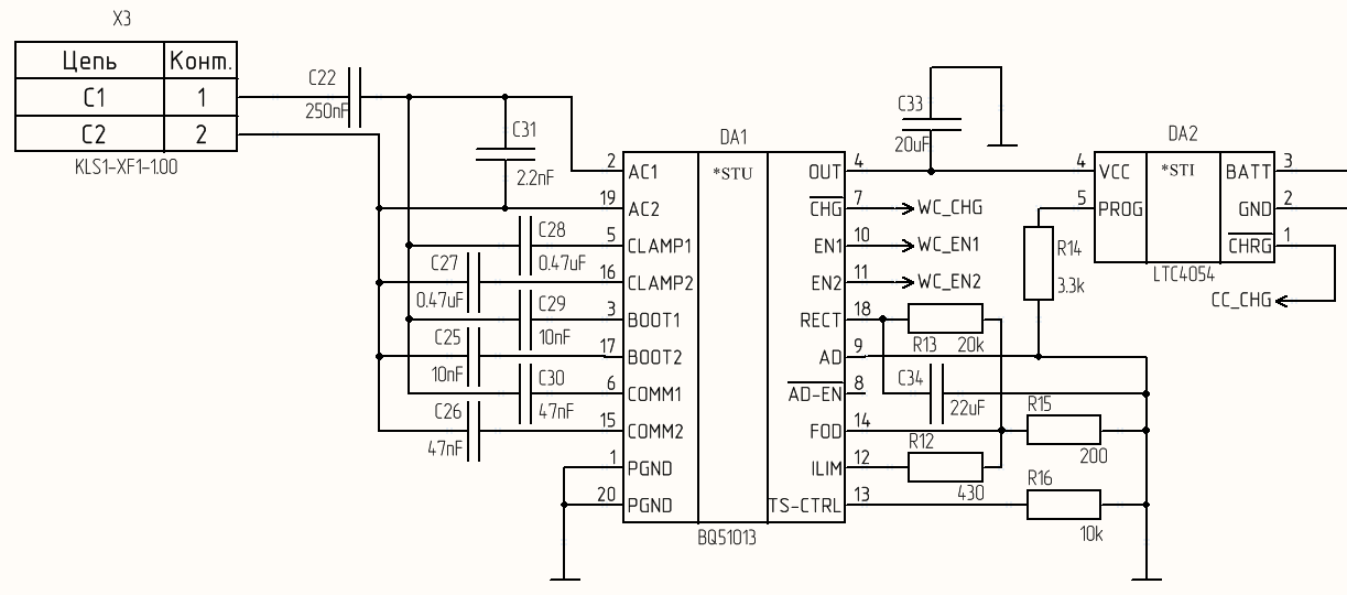
C22 is two parallel (100nF and 150nF) 0603 X7R 25V capacitors in my design.

C33 is two parallel 10uF 0603 X5R 10V capacitors in my design.

All other capacitors is 0603 25V X7R.

I also tried change the values of R12 and R15, but every time it gets the same result. Can you help me?

  • Hello
    How many board are showing this behavior?

    A couple of things to look at:
    1.) Double check the charge current (300mA) and ILIM current (500mA), if it is correct it should work. But should the bq51013(B) go into current limit the power will be dissipated across the 51013 and thermal rise can be high.
    2.) Look for an overload on RECT pin, this is the full wave rectified output from AC1/AC2.
    3.) Check for possible short in the COMM, BOOT and CLAMP capacitors connected to AC1/AC2
    4.) Check for possible short of internal bridge measure AC1, AC2, RECT and Gnd.

    If you can start power transfer and get 4.3V on the output it indicates a lot of the bq51013 is working. Major short would prevent unit from working.
  • Thank you for answer!

    Now I have just one test board.

    I checked things you told me to do...
    1) The ILIM current is 15mA ans this is strange... When i tried to measure the out current I broke my board :) so I need time to do the new one.
    2) The RECT voltage is 7V then the coil is on the center of charging board. But then I move it closer to the edge of charging board, RECT voltage growing up to 20V (in both cases the out voltage is 4.1-4.3V).
    3) There is no short circuit here...
    4) ...and here too.

    After that we have low ILIM current and overheated BQ51013B... Do you have any ideas?
  • Hi Andrey,

    I don't see you add 0.1uF at VRECT. This capacitor is must and need place as closer BQ51013B as possible, also bad layout may meet some issues.

    Regards,
    Driscoll
  • Hello, Driscoll!

    С34 on my circuit is VRECT capacitor, isn't it?

    Also, I use circuit from the datasheet... And there are no other capacitors...

    Regards,
    Andrey.
  • Hi Andrey,

    C34 is 22uF, not 0.1uF.
    you can reference DS page32 (8.2.1.2.6)
    "RECT capacitance is used to smooth the AC to DC conversion and to prevent minor current transients from
    passing to OUT. For this 1-A IMAX, select two 10-μF capacitors and one 0.1-μF capacitor. These should be rated
    to 16 V.
    OUT capacitance is used to reduce any ripple from minor load transients. For this solution, a single 10-μF
    capacitor and a single 0.1-μF capacitor are used."

    Regards,
    Driscoll
  • Thank you very match!

    Now it’s working. Vout is 5V and BQ51013B drops the output to 0V in 20-30 seconds. And still overheating. But, I think this happens because bad PCB design. Possibly the internal thermal regulator shut down the output of BQ51013B when it getting very hot.

    Thank you again!