


Hi Expert,
1. For two cells application, if I choose 3Mohm and 1Mohm for the FB resistors, does it ok for the design?
2. For the Cff Cap, the datasheet shows 22pF, what's the range?
3. Cff is parallel in Rtop in FB, if we add a Cap 0.1uF and parallel in Rbot, seems the battery detection waveform is wrong. Can you guide me what's happening?
If the battery pack was UVP, seems the waveform can trigger the pack, but any risk for it?
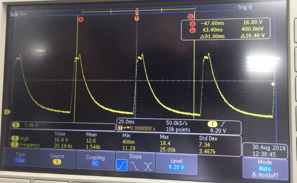
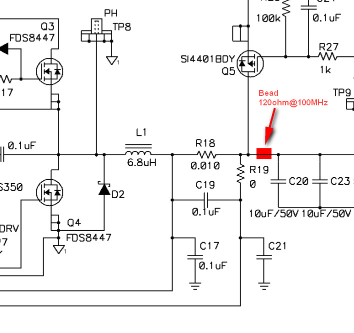
4. Customer wants to prevent the EMI issue, so add the bead at the below circuit. After that we can't get the battery detection waveform, seems the bead consumed the Iwake, I did it in EVM and got the same result.
If we add the 10uF before the bead, that can get the right waveform. Any suggestion for the bead circuit and why the bead consumed the Iwake?
Thanks!
