This thread has been locked.

If you have a related question, please click the "Ask a related question" button in the top right corner. The newly created question will be automatically linked to this question.

LM5160-Q1: Question about Fly-Buck calculator

Part Number: LM5160-Q1
Other Parts Discussed in Thread: TINA-TI, , LM5160

Hi team,

My customer wants to construct isolated DCDC with below condition.

- Vin range : 6V(min), 12V(typ), 17V(max)

- Vout_iso : 12V

- Iout = 400mA (max)

- Switching Frequency < 400kHz

- Max Duty < 50%

- Ripple Raito < 40%

According to the "Calculator_Rev1p03.xlsx" result, Fly-Buck converter looks feasible to support above condition.

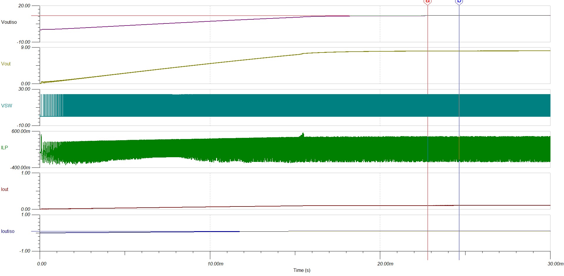
Could you double check if LM5160-Q1 could support above use case? Because I tried simulation with TINA-TI by modifying snvmb64.tsc, I could not get expected Isolated output.

Link : www.ti.com/.../snvmb64

Calculator_Rev1p03_result.xlsx

My customer is now starting transformer design, so your prompt support would be highly appreciated.

Best regards,

  • Hi,

    Here is a webench sample design for 300kHz. Also i attached the TINA model that you gave me and it seems it outputs 12V

    LM5160_Flybuck_300kHz.pdf

    Thanks

    -Arief

  • Hi Arief-san,

    Thanks a lot for prompt reply.

    I also make reference circuitry with Webench, but I still see some mismatchs between calculator and Webench resul, and TINA-TI and Calculator (or Webench) results.

    (1) Calculator_Rev1p03.xlsx vs. Webench
    When Webench configurations (divider ratio of feedback voltage, and turn ratio of transformer) are put into calculator, it looks peak current exceeding lower limit of High side current limit.

    (2) TINA-TI vs. Calculator (or Webench)
    For example, Webench configurations are applied to original Fly-buck reference model of snvmb64.tsc, I can’t get target voltage with target current (400mA) with Vin_min(=6V) condition.
    Could you provide configuration you run the TINA-TI model?

    I’m concerning LM5160 with Fly-buck topology could support customers requirement, otherwise I need to recommend Flybuck-boost topology.

    Best regards,
    Nobuo Fujihara
  • Hi Nobuo-san,

    1) Yes please be careful that the peak current on the High side current limit is not violated when you select the transformer, you might need a higher inductance transformer.

    2) I see that on your tina model, you have 1:1.5 turns transformer and your primary output is set at 8V, therefore at minimum VIN 6V, i believe that you are running into maximum duty cycle condition. Normally we try to run the Flybuck less than 50% duty cycle. You might have to probably use the Flybuck Boost topology to achieve this.

    Thanks
    -Arief