This thread has been locked.

If you have a related question, please click the "Ask a related question" button in the top right corner. The newly created question will be automatically linked to this question.

BQ76940: Battery Connection

Part Number: BQ76940


Hi,

I would like to use BQ76940 for 13 cell battery. From the datasheet, we can see that the cell connection is :
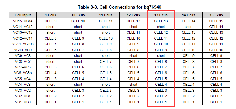
But in my design (PCB), the connection is like:
Could you let me know can I go on using my current PCB? If not, is there any remedy?
Thank you very much.
  • Hi User,
    Certainly the configuration of your PCB is not as recommended, but if I understand correctly the top cell group of the bq76940 is configured for 3 cells like the 9 or 10 cell columns while the bottom 2 groups are configured for 5 cells like the 14 or 15 cell columns. The part should work OK, you may have different margins on POR since there is a 2 cell difference between the cell groups. It is the lower cell group which sees the highest discharge during brown-out conditions as you may have noticed in www.ti.com/.../slua749 so it may work fine.
  • Thanks for your reply.

    Just now, I compared my connection with the 9 or 10 cell column and the 14 or 15 cell columns. Yes, they have some similarities which I did not realized before.

    About the later part of your answer, could you explain more? And is there any care I should take?

    Thank you.

  • Hi User,
    With the recommended configurations there is only 1 cell difference between the voltages applied to the cell groups. In your case you will have a 2 cell voltage difference between the top group and the others.
    Check that during short circuit application and the transient after its protection trip that the supply voltages do not exceed maximums as the voltages trip. The voltage change will want to divide across the filter capacitors, the intermediate cell connections will moderate them. You should be OK since the bottom cell group power depletes the most during the load, but test.