This thread has been locked.

If you have a related question, please click the "Ask a related question" button in the top right corner. The newly created question will be automatically linked to this question.

TPS23753: no Gate drive output for the dc/dc converter switching MOSFET

Expert 6470 points
Part Number: TPS23753
Other Parts Discussed in Thread: , , LMV431A, TLV431

Team,

we have observed that TPS23753 doesn't drive the GATE (even after removing U2 TCMT1107).

What could be the reason of such behavior? 

The schematic on Fig. 2 in slvs853c.pdf is not fully described, especially the „enb” signal which can stop driving GATE.

To give some more background: We have designed the TPS23753 based on TPS23753AEVM-04 (slvu314f.pdf) with the following changes:

  1. Q2 –instead of SI4848DY we have SUD15N15
  2. instead of Coilcraft we have WE

Those should not impact anything. Also, there are no adapters, ADP is connected to RTN. The device is powered from passive 47V Ethernet. We stick to the schematic shown on Fig.1 in slvs853c.pdf.

We can assume that:

The UDD-RTN voltage = 47V, Ucs =0 (there's no current since the transistor is not driven),

UCTL=UB > 2V, Vc=about 5V

We can exclude also overheating.

Thanks for your feedback and help.

Customer

  • Hello Bartoscz,

    First, I would encourage you to consider moving to the TPS23753A, if feasible. The TPS23753A features improvements for uninterrupted device operation through an ESD event and has more customer adoption (AKA longer product life).
  • Does the PWM controller turn on?
    - Are you able to get out of inrush & charge the bulk capacitor?  (RTN-VSS = 0V)
    - Have you exceeded the Vc UVLO threshold of 9V?

  • Hi Thomas,

    thanks, we will consider that, though what is the solution for TPS23753?

    What needs to be on the pins of the device so that the GATE driving would work?

    Thanks & regards.

  • Hi Bartosz,

    Pay close attention to the size of the capacitor of Vc (at least 0.22uF). Larger gate charge will need a larger Vc capacitor. Also, I recommend keeping the same design TPS23753AEVM-004 for troubleshooting purposes & making changes after getting it working.

    In addition to the recommendations in the datasheet, we have this app note for designing with TPS23753:
    www.ti.com/.../slva305c.pdf

    Thanks,
    Tom A.
  • Hi Tom,

    thanks for your help. We are checking if changing C16 to 4,7uF (from 10uF) will make any difference.

    The below questions remain a mystery to us:
    - Why does the PWM controller doesn't turn on? The "enb" should be related to it, but we don't know how it is generated.
    - We have no influence on exceeding Vc UVLO
    - Same goes for "out of inrush & PG go high". The power supply comes from passive PoE (pins 4,5 and 7,8 - 47V)

    Kind regards
  • Hi Bartosz,

    Keeping C16 the same would be best.

    Could you send your schematic? I can address your questions more directly that way.

    You can post it here or email me, offline.

    Regards,
    Tom A.

  • Hi Bartosz,

    On the schematic you have sent, I see they went from the 5V variant of the TPS23753AEVM-004.

    The Wurth 7491195331 is intended for (3.3V, 21uH, 10V bias). If they want a 5V design, I suggest they use a transformer with similar specifications as the Coilcraft HA 3802-BL (5V, 135uH, 12V bias).

    Regards,
    Tom A.

  • Hi Tom,

    the values we've used are for 3.3V as in http://www.ti.com/lit/ug/slvu314f/slvu314f.pdf -> R24=24.3K, R28=348R, C18=100pF, C19=10nF, C21=47nF.

    In any case, we believe those should not make an impact here, also the transformer seems unlikely from our perspective.

    A remark, the Wurth bias is: Pr:Bias = 4:3=1:0.75 (so not 10V) according to the datasheet (https://katalog.we-online.com/pbs/datasheet/7491195331.pdf )
    For Coilcraft for 3.3v the bias is: Pr:Bias = 1:0.5 (so not 12V) according to the datasheet (https://www.coilcraft.com/ha380x.cfm )

    Can you please help investigating further what could be the issue here? We are stuck and haven't moved forward.

    Thanks & regards

  • Hi Bartosz,

    Thanks for the clarification. Apologies for the misreading of the schematic picture.

    To keep this thread up to date with our offline conversation: the customer has changed their TPS23753 ICs & now has a working PWM, but they are having issues with startup from the VDD-VSS PoE input.

    Will update when issue is resolved.

    Thanks,
    Tom A.
  • Hi Tom,

    we have now HA 3801-BL transformer on the schematic (as on the EVM), there are no other changes to the previous schematic that was shared.

    TPS23753A's dc/dc was working for 2 seconds after startup, TPS23753 worked for 5 sec.

    As soon as it's stops, the Vc voltage is close to zero.

    Does the dc/dc start only from the right sequence and can't operate asynchronously?

    Kind regards
  • HI Bartosz,

    - Was the customer able to change their voltage reference (U3) to the low voltage variant, LMV431A? It sounds like they are able to get out of softstart, but unable to maintain stability when the feedback circuit kicks in.
    - Also, please do keep the C16 capacitor to at least 10uF.

    I've reviewed the rest of their schematic & it looks fine to me. Let me know if they have tested with the lower voltage reference.

    Regards,
    Tom A.

  • Hi Tom,

    sorry for the delay. Customer has changed the voltage reference to LMV431A, it helped a bit but didn't resolve the issue (it works for 10 seconds; the Vc is like sawtooth between 6V and 9V). The device still resonates at around 100Hz.

    We continue to look for the reasons.
  • Hi Tom,

    most likely the CS pin is getting damaged. On the slvu314f.pdf schematic there is a R20 = 0 Ohm resistor. Initially we have omitted it, now we consider to put there a 1KOhm resistor.

    The figure 2 on TPS23753 datasheet (Functional Block Diagram of the device) doesn't provide enough level of detail to determine the consequences of doing that (putting R20 > 0) - can you advise on that?

    Kind regards
  • Hi Bartosz,

    The resistor R20 is there to provide additional slope compensation. The CS pin itself is current limited by the internal 2.875k ohm resistor, & the customer's R20 resistor is the same value as the EVM schematic, so it is unlikely the CS pin is sinking too much current. Although, I would not stop them from replacing the IC if they suspect the pin is damaged.

    If their control loop values & bias winding circuit are the same as the 3.3V TPS23753AEVM-004, then the PWM should be operating properly.

    Could you share their newest schematic offline? I'll take a look one last time & if it looks good, we can look at layout.

    Regards,
    Tom Amlee
    PoE PD Apps Engineer

  • Hi Tom,

    thanks for your feedback on R20, it helps to understand it.  I've just sent you the latest schematic and layout offline, can you advise if you see any mistakes?

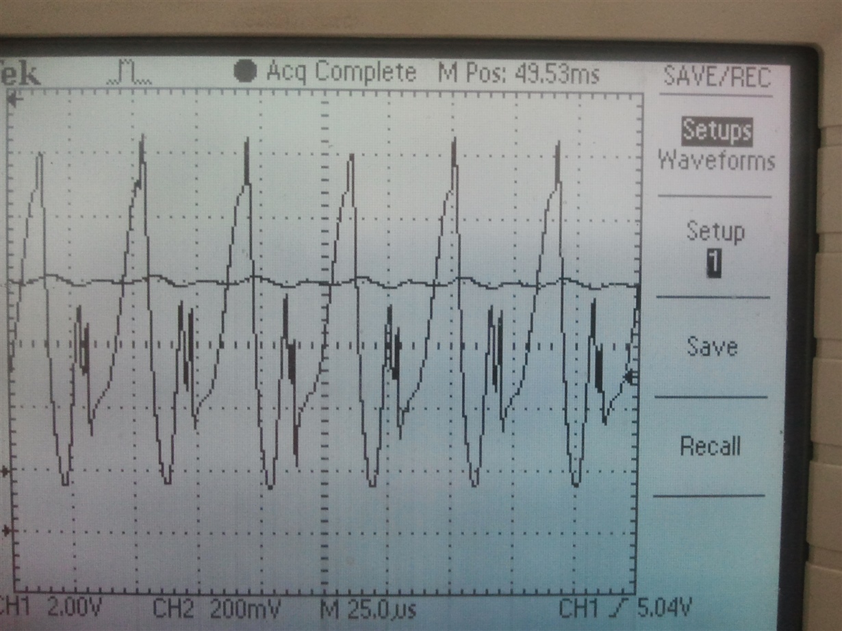
    Additionally, below is a photo from the oscilloscope - the slightly sinusoidal signal is Vc pin (around 8V, 2V per block), the other one is CS pin (200mV per block) - here we observe 25 KHz between -40mV and 1V, whereas it should be 125 KHz. 

    The transformer is Coilcraft HA3801-BL, the reference is TLV431.

    Also, should the device be working (processing) without the realization of optical feedback loop (with 2K resistor between CTL and VB)? 

  • Hi Tom,

    do you have some feedback?

    What should be the right level of GATE voltage? Customer is observing 4.5V which could be the root cause of the issues/instability.

    Kind regards,
    Bartosz
  • Hi Bartosz,

    I see no problem with the customer inverting the polarity of the transformer as long as all of the windings are flipped.

    The customer has chosen a FET with a larger gate charge (>20nC) & a higher miller plateau at ~5.5V. This has higher gate drive requirements than the FET used in the TPS23753EVM-004.Typically, GATE voltage would be as high as Vc b/c Vc supplies GATE directly. Vc is dropping because the Vc cap it is not able to supply enough current to drive the FET.

    Firstly, I suggest testing with the previous FET & the 47 ohm R9 from the EVM & seeing if it is operational to ensure there are no other issues with the circuit. Other than my suggestions below, the schematic looks fine.

    For their current FET choice I suggest increasing the C16 capacitor to 22uF & reducing R9 to 47 ohms. If they are still having issues driving the gate, increase C16 further.

    Lastly, the customer needs to realize the optical feedback loop (2K resistor between CTL and VB) to maintain stability of the system.

    Regards,
    Tom Amlee
    PoE PD Apps Engineer

  • Hi Tom,

    Thank you for your patience and help. With all your suggestions, the design is working properly now.

    Kind regards,
    Bartosz