This thread has been locked.

If you have a related question, please click the "Ask a related question" button in the top right corner. The newly created question will be automatically linked to this question.

TPS62140: continuous tracking

Part Number: TPS62140
Other Parts Discussed in Thread: TPS62147

Hello,

I have a portable device which needs some battery upgrade (currently it uses two CR123 elements which are aweful). It has a simple ADC onboard to track the input voltage and show the percentage of batteries (it is critical to know the percentage otherwise I didn't bother).

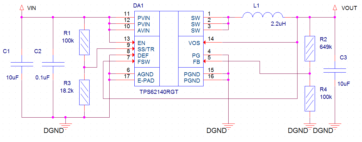
I'd like to use a tracking function of the TPS62140 to lower the maximum input voltage from my new battery pack (two 18650 in series) to the device's limit of 6V with the simple resistor devider connected from the battery pack to the SS\TR pin. At the datasheet it is said that "There is no theoretical limit for the longest startup time".

May I assume that such system would work for as long as the batteries dure and the output voltage of the TPS62140 would decline linearly depending of the voltage applied to the SS\TR pin without any issues?

Is it OK to build a continuously tracking dc-dc converter?

  • Hi Alexander,

    It's not too clear to me what you are trying to achieve. Maybe could you draw a block diagram? Are you trying to charge a battery from a battery?

    The TPS62147/8 is newer, smaller, more accurate, supports a higher Vout, and with more features and would be recommended.

    Yes, you can operate these devices while continuously driving the SS/TR pin.
  • Hi Chris,

    Thank you for your reply.

    My future circuit:

    As I wrote before I have a device which is normally powered from two CR123 in series. It has a maximum input voltage of 6V. CR123s are too expensive. I'd like to replace them by two 18650 accumulators connected in series. It is essential to know when to power off the device when the batteries are out.

    CR123's end voltage is 2V. 18650's end voltage is 3V. A simple constant voltage output dc-dc would transfer an input 8.4-6V to 6V output for example. It won't be possible to use a device's ADC to see when the batteries are out. As you can see from my schematic I'd like to drive the SS\TR pin from the input voltage via the resistor divider. I've experimented a bit with the real TPS62140 and it seems to work correctly with such a connection. At 8.4V input the output is almnost 6V. At 6V input the output is 4.4V which is informative enough to see that I should power off the device.

    Why do you recommend to use TPS62147 instead? Would TPS62140 soon get an NRND status?

  • Thanks for explaining. It sounds like you can accept a different Vout, depending on the battery type? This is not usually the case in most systems.

    I'm also not clear why you can't measure the voltage with an ADC. Is there not one already in your system?

    TPS62147 is the next generation device, in this family. It has the advantages that I described before. An additional one that will likely come in handy in your application is its precise enable pin. This allows you to turn off the device at a precise Vin, with just a voltage divider from Vin.
  • There is another dc-dc converter inside my device. Its input voltage is 6V. Absolute maximum is 7V. ADC circuit is made so that it can measure only from 6V down to 3V. All I want is to downgrade an input voltage range of 8.4-to-6V to 6-to-4V range. That would allow me to see the real discharge state of the 18650.
  • Ah, I think I understand now. Yes, if you can accept a variable Vout and want this Vout to reflect the battery voltage, this technique you have should work for that.