


Dear,
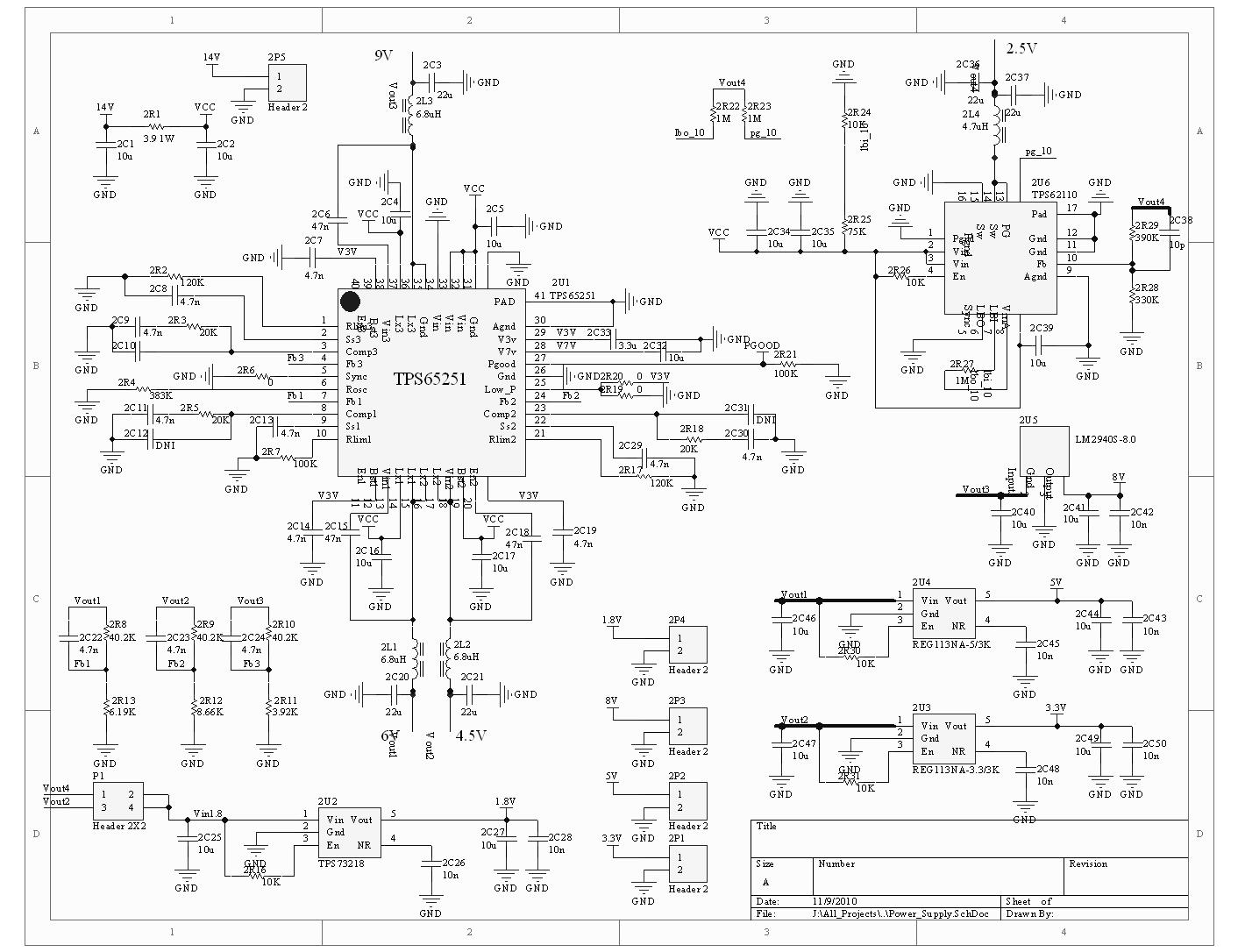
I am using TPS65251 in my application board. Buck1 o/p = 6V/2A, Buck2 o/p = 4.5V/1A, Buck3 o/p = 9V/1A, the power supply is 14V common to all. Frequency of operation is
500KHz (R on PIN6 = 383K). RLIM1 = 100K, RLIM2 = 120K, RLIM3 = 120K.
When Low_power pin is connected to V3V, all outputs are correct and they can be driven up to 150mA. But when I pull Low_power pin down, all outputs are floating.
They can not be driven at light load.
I also tried to turn on bucks step by step by changing capacitor at EN pins ( 4.7nF @ EN1, 10nF@En2, 47nF@EN3, respectively) but all outputs can not regulated.
I don't know why difference between High and Low threshold of Low power pin.
Please kindly get my schematic attached file and help me review it.\
I am looking forward to hearing from you soon.
Best regards,
HOANG TRUYEN
VIETTEL GROUP
