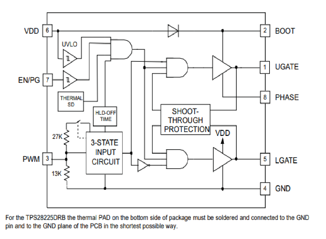
Hi Team,
My customer would like to understand the resistor value between pin4/pin5. They found the value seems varying a lot and concern if there could be potential issue. Thanks
This thread has been locked.
If you have a related question, please click the "Ask a related question" button in the top right corner. The newly created question will be automatically linked to this question.
Hi Team,
My customer would like to understand the resistor value between pin4/pin5. They found the value seems varying a lot and concern if there could be potential issue. Thanks
Hi Duncan,
Glad to hear back from you. Which datasheet did you find that block diagram attached on your first post?
It seems odd since I am looking at TPS28225's datasheet and as you can see below, we do not specify a resistor between pin 4 and pin 5 and even more puzzling is the fact that you're measuring a 100kohm resistance between the 2 pins.
The picture below is from the following link:
 But that resistor would only be there to prevent any open-gate conditions and any accidental turn on during output active low events on the power FET.
It can also be set externally by simply connecting the desired resistance value from pin 5 to ground.
What application and in what topology are they using the device that the customer is concerned?
Thanks.
Regards,
Hi Mamadou,
below list to show the resistance between the pin4 and pin5 of TPS28225-Q1.
Sample1 (call "NG sample"):
The resistance is 85.7K.
Sample2 (call "NG sample"):
The resistance is 270K.
Sample3 (call "Good sample")
The resistance is 1.8M.
And please help to the difference on the marking.
1. NG sample : PXND TI 75K 0708
2. Good sample : PXND TI 6CK AGHF
thanks