


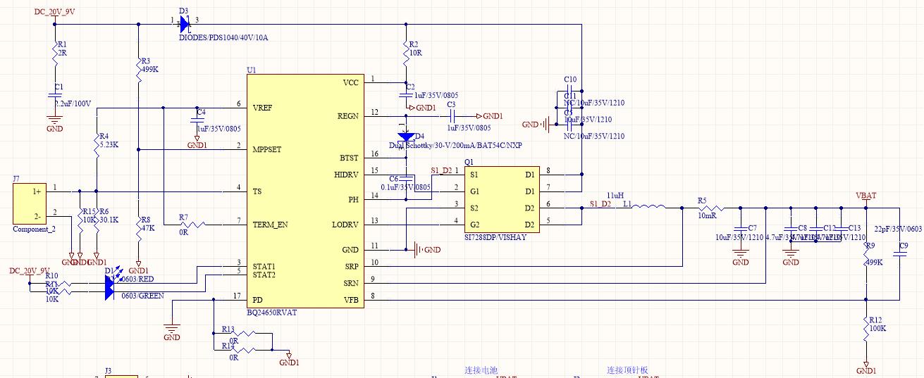
I am currently using TI's BQ24650 chip, the input is 60W AC/DC charger (mainly using this charger), the output is 20V.
1. The 20V is the input voltage of the BQ24650.
2. The MPPTSET pin of the chip is larger than 1.2V.
3. Designed to charge 2 lithium batteries, the maximum charging current is 4A.
The following picture is the schematic:
If I set the output voltage to 8.4V, that is, the external divider voltage resistor of VFB is 499K, 100K, there will be a 30-minute charging process of 4A/10 and about 400 mA after power-on (because VFB voltage is lower than Vlowv). ),As shown below:
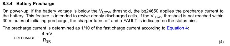
Under normal circumstances, 400mA can be charged to about 8V to use 4A current charge. When the battery voltage is at the bottom, it is charged with 400mA. This process will take too long;
If the Vlowv threshold is lowered, about 7.2V, the output voltage will reach about 9.2V, which will cause damage to the battery.
The issue is:
1. I want to lower the threshold when charging with 1/10 charge current and want to lower the output voltage to 8.4V, but the two feel contradictory. Please give other suggestions?
2. Does TI have other models that can satisfy this function? 20V DC input + solar function, the output can charge 2 lithium batteries, the charging current is greater than or equal to 4A?
