This thread has been locked.

If you have a related question, please click the "Ask a related question" button in the top right corner. The newly created question will be automatically linked to this question.

BQ51003: Trouble in resonating circuit

Part Number: BQ51003
Other Parts Discussed in Thread: TIDA-00318,

Hi everyone,

I have designed a PCB with the BQ51003. I have more or less replied what is reported in TIDA-00318, changing only the resonant circuit capacitance values.

The circuit is made on a flexible PCB, and the rx coil is printed on it.

I have followed step-by-step what is reported on the datasheet, but I'm facing some issues in the charging process.

When placing the coil onto a QI-compliant charger, it doesn't resonate and I see on the AC1-AC2 pins a burst every (more or less) 500 ms with a 2Vpp amplitude.

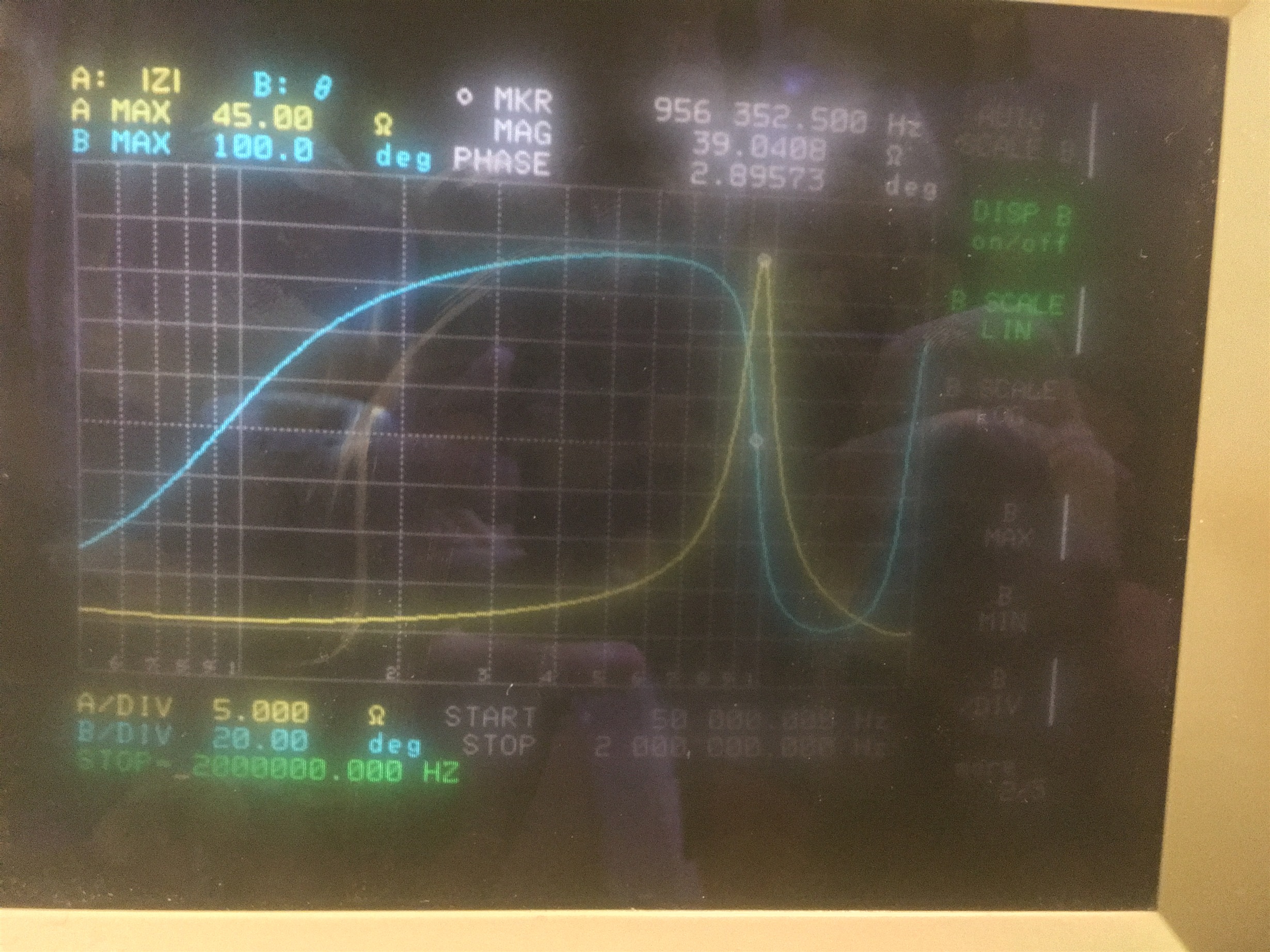
I'm attaching a picture of the impedance analyzer, when placing my coil onto the QI charger turned off, with the probe tips on AC1-AC2.

The free air peak is around 988 kHz.

My inductor is 670 nH and my capacitors Cs = 3.7 uF and Cd = 37.3 nF.

Can someone please help me?! I really don't know what to do more!

Thank you!!

Andrea

  • If the coil L is only 670nH this will be a problem. You will need an L value in the 10uH range.
    Check voltage at RECT pin of the RX, it needs to be over 2.7V during the ping to exceed UVLO.

    I have worked with PCB coils and they are difficult, low L and high DCR limit them.
  • Thank you Bill.
    Where on the data-sheet are reported these constrains?!
    I checked the voltage at the RECT pin and I see a sort of a charge-discharge of a capacitor, right now I cannot remember the voltage value, but it was less than 2V.

    The board is already fabricated, do you think I should throw all away?

    Thank you very much.

    Best regards.

    Andrea
  • Take a look at the below application note on Qi coils, page 8.
    www.ti.com/lit/an/slyt477/slyt477.pdf

    What may help your coil is to increase the shield size and thickness behind your coil to increase L value. Also reduce coil to coil distance. After that is possibly splicing more turns of wire into the coil.
    Coupling factor goes down with coil diameter and small, 20mm will need higher L to overcome this. Coil used on TIDA-00318 is in the 25uH range. Standard EVM coil is about 40mm X 30mm and has an L value of about 10uH.
  • Thank you for the link!
    I will try to add a slice of wire to my coil, but this operation will be very difficult in my opinion.

    Do you think there will be another way, for example by changing capacitors or some passives on the board, to resolve this problem?

    Best regards.

    Andrea
  • How big is your coil?
    How much shielding (ferrite plate) do you have on the back of it?

    Tuning will not help.
  • I don't have any ferrite behind my coil.
    It is designed to work as a flexible coil, putting a ferrite on its back will mine its flexibility.
    It will be part of a biomedical device.

    The coil is 433x442 mils (11x11 mm).

    Do you think that adding a wired coil will help?

    Thank you again.

    Best regards.

    Andrea Bodini
  • The coil is on the small size, 11 X 11 mm will be difficult.
    Wurth electronics (and others) manufactures flexible material that may help see WE-FSFS material.

    You may want to test with an off the shelf coil some to look at would be.
    Wurth 760308101221 or Wurth 760308101208.
  • Ok Bill, thank you very much.

    I will try with your hints. I really hope to resolve the issue with your kind help.

    Best regards.

    Andrea Bodini
  • The issue was finally resolved by making these changes:
    - using a wired coil, instead of a pcb.
    - changing the coil of the power TX, with a smaller one.