Other Parts Discussed in Thread: BQ24618
Hello - I'm currently trying to breadboard a BQ24600 battery charge controller circuit, and I'm running into some issues with the charging current that I haven't yet been able to find a solution for. I was originally working with the BQ24618 as part of a larger design on a PCB, but after running into similar undercurrent issues with that IC, I wanted to try validating the design and component choices on a breadboard before redoing the PCB design. I also opted to switch to the BQ24600 as it was a simpler implementation that still met all my design goals. I'm aware that breadboarding isn't especially ideal for a 1.2MHz switching supply, but my hope was to get close enough to the intended operation that I could feel comfortable moving ahead with a new PCB. I'm not sure if my current issues are due to the fact that it's on a breadboard (parasitics) but I suspect that may not be the case.
Attached is a circuit diagram for what I'm using - apologies in advance for the sloppiness, I had to convert it from a different working document in a hurry to reflect the exact breadboard implementation. Items that are boxed on the diagram have been implemented on perfboard that was then wired to the breadboard separately, both to cut down on stray wiring and to reduce possible parasitics (or so I've hoped). Several of the components are surface mount, but have been adapted for breadboard use.
I have the ISET pin configured with a voltage divider to yield a nominal charging current of 2.88A normal, 288mA precharge, but in reality I'm seeing approximately 70mA of charging current. I can't say for sure if the charging is actually occurring in precharge mode (it shouldn't be - VFB never fell below VLOWV during the discharge test at the beginning of operation) but in either case, the current is lower than it ought to be.
Additionally, I've tested using four different inductors (3 3.3uH, one 10uH) to see if that made a difference, and I'm getting slightly different charging currents in each case:
- ASPI-0630HI-3R3M-T15 = 67.7 mA
- 0518CDMCCDS-3R3MC = 53 mA
- IHLP2525CZER3R3M01 = 68.8 mA
- SRP1245A-100M = 41.29 mA
I may be mistaken, but if the charger is in either constant-current phase, shouldn't the charging current be the same regardless of the inductor used? All of these appear to have saturation currents well above the intended charging current, so I can't tell if the inductor selection is part of the issue.
Additionally, two different MOSFETs are being used out of expediency - I had to dead-bug solder each and we ordered about 7 (nearly identical characteristic) different transistors, so I've only mounted one of each so far. Since they're so similar to each other, I doubt this is contributing to the current problem.
The reverse protection diode is the exact diode specified in the datasheet, and the bootstrap Schottky is a generic PTH Schottky that we had on hand - it tested fine but I don't have a part number.
The TS pin isn't being used, so I've biased it to a mid-level voltage - this pin read 1.73V during my tests which seems to be within the good range based on the datasheet.
ISET pin read 0.577V during testing, but the current output is low based on the equations in the datasheet (our sense resistor is 10mOhm, just as in the example design). As a test, I also tried setting this pin using a potentiometer, and I noted that even over the course of a wide range of input voltages (0.57 to approximately 1.5 V) there was relatively little change in the output current (an increase of around 15mA max). I'm not sure exactly how to interpret that, but I figure it's probably relevant so I wanted to bring it up here.
VREF and REGN both read the correct output voltages (3.3V and 6V respectively).
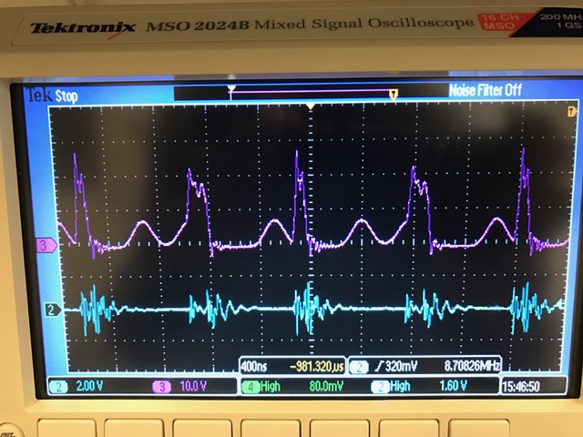
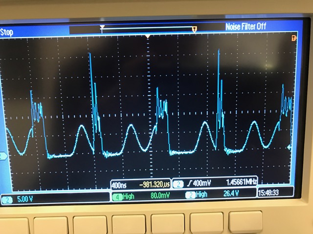
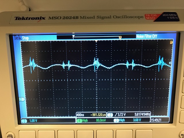
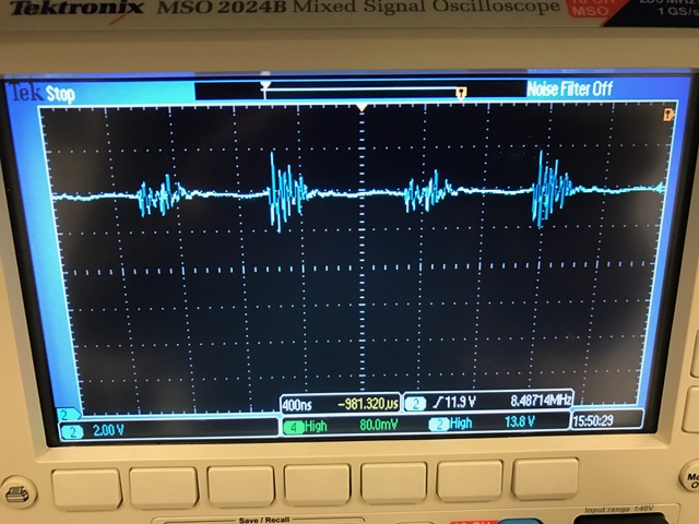
I'm currently working on getting oscilloscope data for various nodes, which I can post in a bit. I wanted to go ahead and put this post here to see if there's anything obvious that I'm doing wrong. Again, I had a very similar issue with an actual PCB implementation of a chip from the same family, so I'm thinking the problem is only mildly influenced by the fact that this was done on-breadboard, but I may be wrong about that.
Any help or explanations you could offer would be greatly appreciated, and let me know if you have any questions or need further clarification - thanks in advance!
Best,
Jack