This thread has been locked.

If you have a related question, please click the "Ask a related question" button in the top right corner. The newly created question will be automatically linked to this question.

BQ76PL455A: How bq76PL455_GUI communicate to PC?

Part Number: BQ76PL455A
Other Parts Discussed in Thread: BQ76PL455EVM,

Hi,

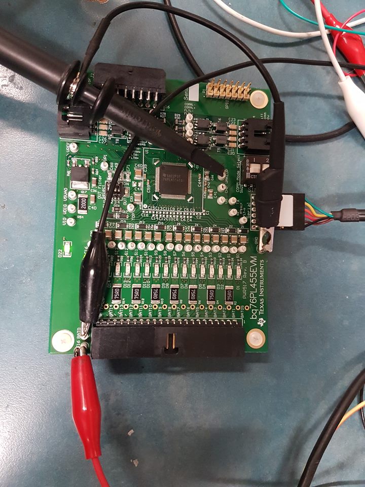
I'm trying to play with the bq76PL455EVM but I'm not enable to connect the GUI with the EVM. I'm always getting the "Unable to open COM port" error.

I'm using the TTL-232R-5V cable, like mentionned in the datasheet.

The only connector connected to the EVM is J3 (serial), all the other connectors are disconnected.

It doesn't seems required in the datasheet to add cells array to J1 to make the EVM works.

I tried every possible combination with SW2. What I understood is if I'm a using only one EVM with the GUI, I need to have my board configured in single ended mode.

What I already tried:

Here is my device manager setup, sorry it's in french:

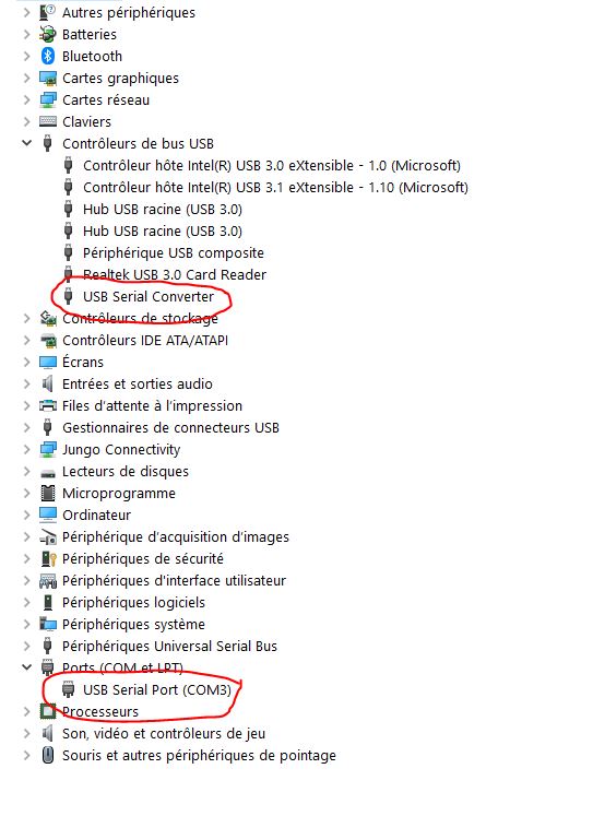
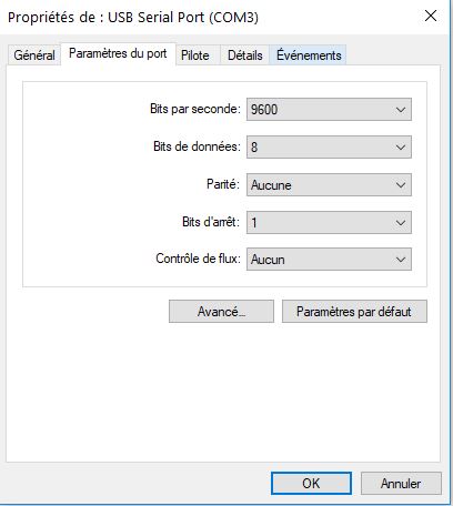
Here is the configuration of the port (9600 baud rate):

Note that my USB Serial Converter has VCP enable.

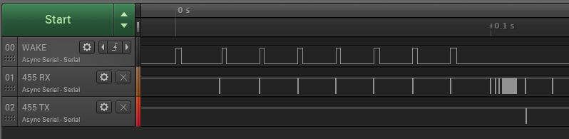
Is there a way I can know if the PCB is the problem and not my computer or cable?

Do you have any tips that could help me figure out the problem?

Thanks,

Elio


  • Hi Elio,

    Thank you for providing detailed information on your debugging. Quick question before proceeding: what voltage (and current limit if any) have you supplied to the EVM aside from the power from the COM cable?

    Regards,
    Vince
  • Hi Vince,

    Aside from the power COM cable, I had 30V on BAT16.

    I have a voltage divider PCB that take 30V and divide it in 16 different voltage (to simulate cells).

    BAT16 is 30V and the last cell is around 1.875V, each cells see around 1.875V.

    Can I only supply the EVM with the COM cable or I also need to supply the 16 cell inputs connector?

    Thanks,

    Elio

  • Hi Elio,

    You do not need to have the resistor ladder, but you do need to connect BAT16/BAT0 to a power supply to power the board. The COM cable must also supply a separate logic supply for the VIO on the device.

    Would you be able to try the following:
    -Connect BAT16 to +30V and BAT0 to GND of an external power supply (use the testpoints above J1, do not connect the resistor ladder for now just in case it is a faulty resistor ladder)
    -Set the COMM mode switch (SW2) fully to the left (1=OFF, 2=OFF)
    -Ensure he FTDI cable has the gold part facing up on the EVM connector
    -Ensure the FTDI cable is connected directly to the PC (NOT through a USB hub or dock)

    Regards,
    Vince
  • Hi Vince,

    I tested everything you proposed and nothing is working.

    Is there something else I can try?

    Thanks,

    Elio

  • Hi Elio,

    Considering the basic setup is not working, would you be able to see if the device wakes up at all? First ensure that when you do the above recommendations, you see a wakeup pulse on the WAKEUP line of the 455 UART interface. So connect a scope to the WAKEUP pin of J3 and see if the wakeup pulse is reaching the device. If the pulse is not reaching the device, the cable could be broken (which is more common than most would suspect). If you do see a pulse, and the LED on the EVM is not turning on, let me know.

    Thanks,
    Vince
  • Hi Vince,

    I did what you told me and here are my result. 

    I did a continuity test from the U1 pin49 and U2 pin4 and everything is fine.

    Here are my screen capture of the WAKEUP signal on the test pad. Sorry I wasn't able to get everything at one since the signal is long.

    I also probe the WAKEUP_N signal from the TTL-232-5V directly on the connector and it is giving me the exact same result as the WAKEUP going into U1 but reversed. The inverter is working properly.

    Here is a picture of my setup. As you can see D22 is ON. The red banana plug output 29.2V.

    Here is a picture of my power supply before pluggin the COM port:

    Here is a picture of my power supply when the COM port is plugged:

    Hope this helps, feel free to send me any other idea you might have to make this work.

    Thanks,

    Elio

  • Hi Elio,

    The good news is the device is waking up (evidenced by the LED lighting up). We need to find where the communications are failing. Would you be able to probe the TX/RX lines of the 455 just like you did with the wakeup and see if any communications are being sent/received from the device? If the device is receiving comms but isn't responding, it could be a baudrate issue.

    Regards,
    Vince
  • Hi Vince,

    I have a probe on the TX and one on the RX test point on the EVM and I'm receiving nothing.
    When the COM port isn't connected TX and RX are low. When I plugged the COM port TX and RX are becoming high.

    I can't see any communication. Even if I try to connect myself to the GUI.

    Is-there a way I can try to send COM on the 455 signals without my TTL-232-5V?
    Can I try to change my baudrate? In my setting my port is at 9600 bit/s, 8-N-1.

    Thanks,

    Elio
  • Hi Elio,

    It is possible this is a cable issue, but before concluding that, I would like you to try changing the baudrate setting of your port to the PL455 default of 250k. Let me know if this affects the communications, or if you see any communications occur on the RX/TX lines in this case.

    Thanks,
    Vince
  • Hi Vince,

    I can't select a 250k baudrate. The closet on my port is 230400.
    To change the baudrate I need to go in the properties of my COM port in device manager right?

    Is there a way to set a custom baudrate in device manager?

    Thanks,

    Elio
  • Hi Elio,

    The baudrate in Windows should be bypassed by the GUI on startup, so changing the port's baudrate in Windows may actually not be necessary. After testing on my own system, this baudrate actually stays at 9600 while the device is communicating at 250k, so this may just be the nominal value for Windows.

    For your setup, considering that the computer is unable to send any communications to the device's RX line, but is still able to send a wake pulse to the WAKE line means there is likely an issue with the cable itself. You should see communications similar to the image below with a functional setup:

    Would you be able to test with a different cable and provide the results?

    Thanks!

    Vince

  • Hi Vince,

    I will check if the cable might be the problem. It is brand new from 2 weeks ago.

    If I trigg the wakeup signal with an Arduino, am I supposed to see an answer back from the IC on his TX line without sending any other message on TX/RX with the Arduino?

    Otherwise, do you know if I can send a certain UART TX/RX signal from an Arduino and expect a certain signal coming back from the BQ76?

    Thanks,

    Elio

  • Hi Elio,

    If using a microcontroller to communicate with the device, I recommend checking out the bq76PL455A-Q1 Software Design Reference (www.ti.com/.../slva617a.pdf). This will help to step you through getting a response from the device.

    For your case, you just need to do the auto-addressing for 1 device, then do a read of any register and look for a response.

    Regards,
    Vince