Because of the holidays, TI E2E™ design support forum responses will be delayed from Dec. 25 through Jan. 2. Thank you for your patience.

This thread has been locked.

If you have a related question, please click the "Ask a related question" button in the top right corner. The newly created question will be automatically linked to this question.

BQ24610: BQ24610 Charging Indicator STAT1 blinking

Part Number: BQ24610
Other Parts Discussed in Thread: BQ3060

Hi.

In the forum saw a lot of posts, have found a charge stat1 flashing phenomenon.

In my application, using BQ24610 to charge the 2p4s battery pack, the charging process also first STAT1 led flashes, STAT2 LED lights off. (Feeling the device is charging and stopping the charging process, and with the STAT1 led flashing, programmed input current is indeed in the jump.) 

There is such a phenomenon, with a multimeter and the oscilloscope to touch the VFB,STAT1 LED lights on hold, normal charging, remove the pen, SATA1 LED lights will blink. It is also true to touch with your fingers.

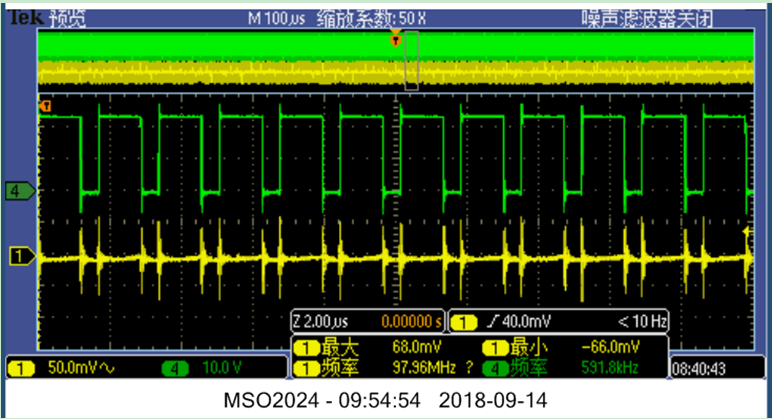
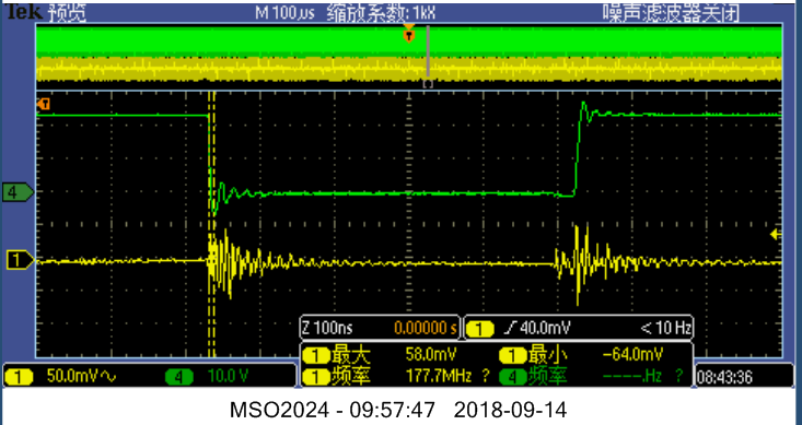
The SW and VfB waveforms are charged as shown in the following figure: (Channel 1 is SW, Channel 2 is the VfB, the VfB uses an AC channel)

Vref,regn,en,pg are normal.

What is the problem caused when I don't know? It is also not possible to try and connect the capacitance (11PF,16PF,22PF,100PF,1NF) on the VfB-to-ground sampling resistor.

My English is very poor, I hope to express my understanding. This question is already very anxious for me, I need the help!

  • In my application, charging is sometimes normal and sometimes not normal (state1 LED flashing).
    I felt the circuit was unstable, but I didn't know the problem was there.
  • Hi,

    You mentioned that “Channel 1 is SW, Channel 2 is the VfB, the VfB uses an AC channel”, but there’s no channel 2 on your waveforms. In fact, it looks like Channel 4 is SW and Channel 1 is Vfb. The waveforms provided are normal. Are you testing the BQ24610 official EVM or your own board?

    Thanks!
  • Hi, Ning T

    I'm sorry, I have an error in the description.
    “Channel 4 is SW and Channel 1 is Vfb,the VfB uses an AC channel” is right.
    I was testing my own board.

    Thanks!
  • Hi,Ning T

    This is my schematic and PCB file.

    BQ24610.rar

  • Tao,

    On the schematic, you set fast charge current the same as precharge/termination current. The precharge/termination current is recommended to be 10% of the fast charge current. Please modify your design and try again.

    Thanks,

    Ning.

    Please click "This Resolved my issue" button if this post answer your question.

  • T,

    Thank you for your reply. But I don't think so.In the BQ24610 datasheet, 9.3.2 and 9.3.4 are as follows:

    so, I set fast charge current  is1.5A, precharge/termination current is 0.3A. The values of these two parameters are not the same.

  • Is there any SYSTEM load connected? What is the battery voltage?
    Thanks!
  • Ning,
    No system load is connected. Now my battery voltage is 14.33V. (Battery pack maximum voltage is 16.8V)

  • Hi,

    Please probe ACN voltage, the input current, battery charge current (or L1 current), VBAT and check if they are normal.

    Thanks,

    Ning.
  • hi

    V_ACN=23.9V
    I_IN=0.34A
    I_CHG=413mA
    V_BAT=16.73V
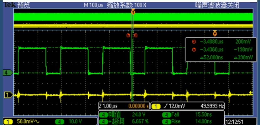
  • Today,I have a 10 ohm resistor in series on the gate of the upper and lower MOSFET(Rg_up =10Ω,Rg_down=10Ω ). Add an RC snubber between switch node and power ground(Cs=3.3nF,Rs=5.1Ω).The waveform has been improved. As shown in the following illustration:

    However, when the power supply to the battery charging, there will be STAT1 led flashing phenomenon.

  • Hi,

    I meant please check these waveforms since you feel the device is charging and stopping the charging process and programmed input current is indeed in the jump.

    Please also check e2e.ti.com/.../728226 and see if it is helpful for you.

    Thanks,

    Ning.
    Please click "This Resolved my issue" button if this post answer your question.
  • Hi, Ning

    Thank you for your reply.

    “ input current is indeed in the jump” is caused by STAT1 led blinking. When the STAT1 LED is on, the bq24610 can charge normally, so the programmed power supply has an output current. When the STAT1 LED is off, the bq24610 does not charge the battery, so the programmed power supply has no output current. Therefore, when the bq24610 STAT1 led blinks, the programmed power output current is also jumping.

    In addition, I feel the device is charging and stop charging, also because the STAT1 LED is flashing. But in fact, the STAT2 led has always been off, the STAT1 led flashes, and the BQ24610 state is switched between charging and “Charge suspend, timer fault, overvoltage, sleep mode, battery absent”.

    I'm sorry, I don't have the tools to probe the input current and battery charge current (or L1 current) waveforms.

    Battery Fuel Gauge is used bq3060, there is such a phenomenon, when the STAT1 led in the blink, I put the SMBus line to EV2300 or touch the bq3060 SMBus line with the hand, this time STAT1 led will keep the on, and bq24610 can normally charge.
  • Could you please bypass the gauge, then charge the battery with the bq24610 directly and check if it works normally?
    Thanks!
    Please click "This Resolved my issue" button if this post answer your question.
  • Hi,

    We haven’t heard back from you for a while, the thread is considered solved and closed.

    Thanks!
    Please click "This Resolved my issue" button if this post answer your question.
  • did it solve the porblem? I have problem like you . stat1 is blinking on full charge state.
    I did debug Prechare and termination current. It changed 0.3A to 0.5A. the result is that Stat1 is off, and that stat2 is on.
    but PCBS of same characteristic have different result. one PCB is normal operation, but the other one is abnormal operation.

    Is Prechare and termination current raised more up than 0.5A?
    so Will the problem be solved?

    (fast charge current is 2A and measured current is 1.5A)
  • Hi,

    In theory, the precharge and termination current settings should not impact on the charge status. It is highly recommended to get familiar with the BQ24610 charger system by evaluating the BQ24610 EVM (www.ti.com/.../BQ24610EVM) with your battery and compare with your own board behavior. The debug process can be much more effective and higher efficient with a reference board.

    Thanks!
    Please click "This Resolved my issue" button if this post answer your question.