This thread has been locked.

If you have a related question, please click the "Ask a related question" button in the top right corner. The newly created question will be automatically linked to this question.

LP8863-Q1: Output waveform question

Part Number: LP8863-Q1

Hello Sir,

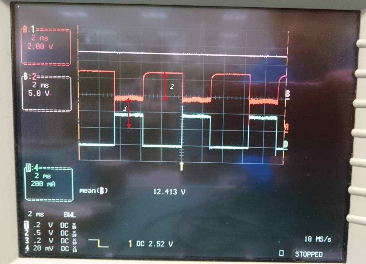
I would like to confirm below voltage 1 and voltage 2

Conditions:

Boost Voltage set to 12V

ILED0~ILED5 connect together to get 900mA

LED is 3S1P .

I can see voltage 1 around 4V and voltage 2 around 3.5V . 

- May I know V1 follow LED qty per string to change ? No concern on LED current ,right ?

- What conditions will influence V2 , why its 3.5V  ?

Many thanks !

  • Hi Terry,

    Sorry but the description is not so clear that I cannot get it. Would you please help me understand your question?

    1. LED configuration is 3s1p. Then what is the total LED forward voltage?
    2. What is the signal A and D in the waveform?
    3. "May I know V1 follow LED qty per string to change ? No concern on LED current ,right ?" What does your question mean? Could you please clarify a little bit more?

    Thanks.
  • Hello Shirley,

    Sorry my unclear info ~

    1. LED configuration is 3s1p. Then what is the total LED forward voltage?<= typ 3V per LED Vf
    2. What is the signal A and D in the waveform? <= A is LED0~5 (shorted together) , D is PWM input .
    3. "May I know V1 follow LED qty per string to change ? No concern on LED current ,right ?" What does your question mean? Could you please clarify a little bit more?

        <= If  we use different LED Vf  and different LED current , will V1 be changed ?  

            How to determine V2 voltage ?  Now is around 3.5V .  I need to know what conditions will change V2 .

    TKS ~ 

  • Hi Terry,

    Firstly, since there are only 3 LEDs, the total typical LED forward voltage is just 9V, which is lower than the input voltage. However for the boost converter, the output voltage is always higher than the input. On the other side, the minimum boost output voltage is also limited by the equation below

    So in this case the minimum boost output voltage depends on the higher value of the two, i.e., Vboost=max{Vin, Vminboost}.

    Therefore, V1 can be calculated as Vboost-Vled(vf). If the LED Vf or LED current changes, V1 will also be changed.

    V1+V2 is the LEDx pin voltage when the LEDs are turned off. V1+V2=Vboost-Vled(vf when LEDs are turned off). In this period, the LED voltage depends on the leakage current, the forward voltage is lower than the typical 3V voltage.