Hello
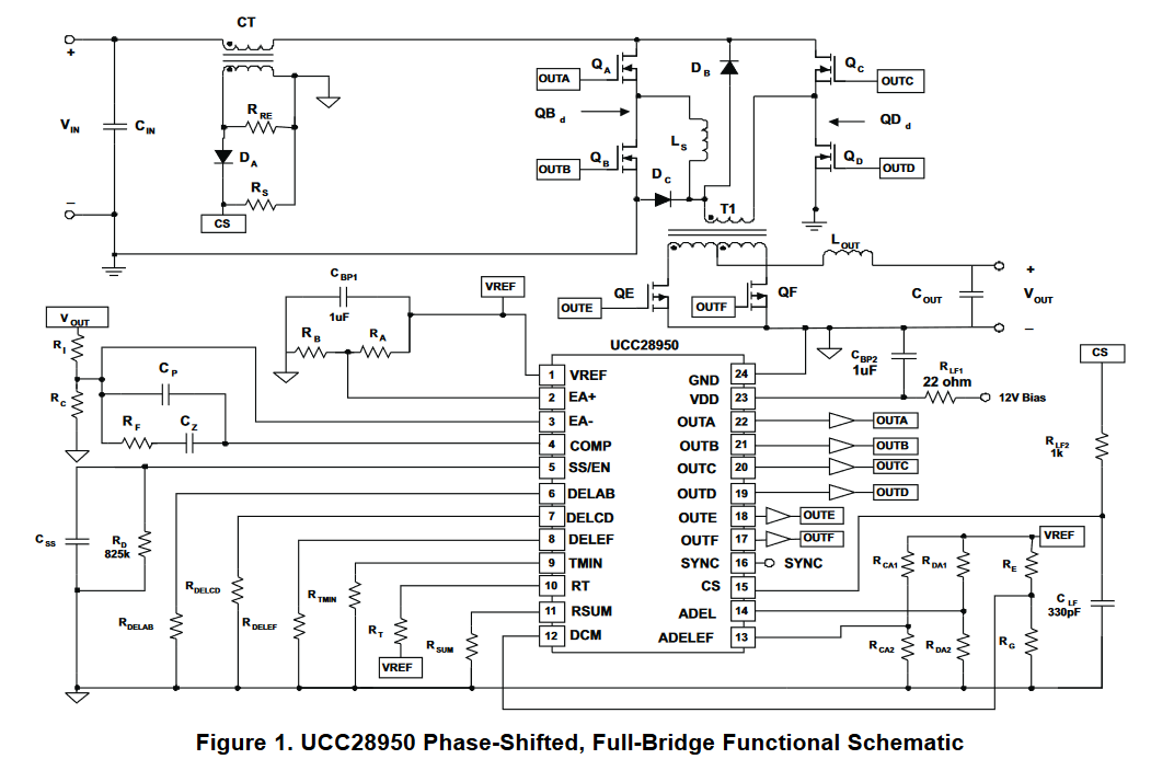
How did you set that 155ns in the page nmbr:51 of UCC28951-Q1 datasheet . please explain the following those two conditions mentioned in that page number for Tabset
and also for Tafset condition where you have taken 170ns as the cutoff .
Thanks !