This thread has been locked.

If you have a related question, please click the "Ask a related question" button in the top right corner. The newly created question will be automatically linked to this question.

BQ25120A: having a problem with the default charge setting when using the part.

Part Number: BQ25120A

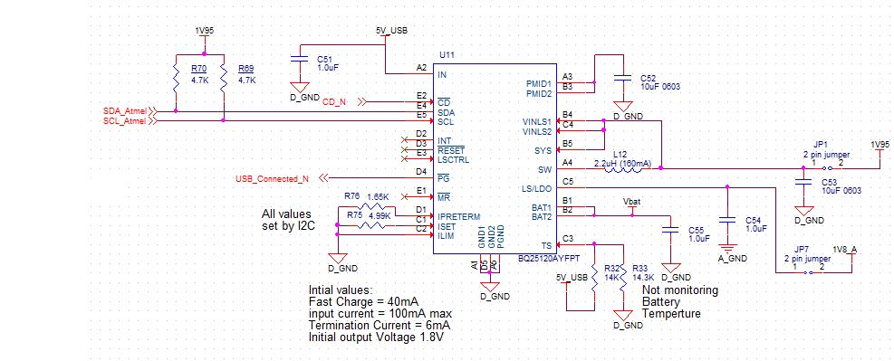
Above is the circuit we are using.  We have no problem setting the charge current through I2C setting.  the default charging does not work.  We actually get no charging at all when we connect power.  I can see 4.97V on C51.  I have a 10K pullup not shown on the PG_N pin.  I can verify that it goes from 1.95V to 0V when I plug the USB in to charge the unit.   There is no voltage on Iset or Iptreterm pins. I can see no charging current going through JP4 when connected to the charger.  I also don't see any voltage change across the battery with the jumpers installed and the current meter removed.  Please let me know if you need any additional information or want me to measure something else after review message and email.


  • David,

    Is your /CD pin pulled low? /CD will have to be low when you want to charge. Your schematic looks okay.

    Can you disconnect the battery and check on the voltage on the VBAT pin? Is PMID looking okay? PMID will have to be 200mV above VBATREG setting to be able to charge.
    regards,
    gautham
  • With the /CD line tied to ground, the voltage on the Vbat pin is 0 when I disconnect the battery.  The PMID pin measures 4.9V with or without the battery installed.  We have severl of these boards so it is not a problem with a single unit.

    Any other ideas?

    Dave

  • David,

    Is the VIN voltage measured on the cap next to the BQ25120A? Could you provide startup waveforms of VIN/VPMID and VBAT? Also VSYS would be helpful. 

    Can you provide a register dump of all the registers on powerup?

    thanks,

    gautham

  • Here is a quick power point showing Vin, VPMID , VBAT and VSYS at startup.

    We have no code running on the board so the registers will all be the default values of the chip at startup.  Do you still need a dump?Power up waveforms of BQ25120A circuit.pptx

  • David,

    The waveforms look okay. No issues i see there. Your configuration should get you 10mA atleast of charge current. Please send a dump to make sure the device is not seeing any faults we cannot see outside.

    regards,
    gautham
  • OK I have found the problem. When we dumped the registers, the TS fault was set.  The values for R32 and R33 were copied directly from the datasheet section copied below.  This has not changed through any of the BQ2512X series datasheets.  Ts needs to 55% to 60% of Vin to Disable TS function. A divider of a 14K over a 14.3K gives you only 50.5% of VIN.  A 14k  over a 20K will yield 58.8% of Vin.  Once I changed the bottom resistor the default charger current started.  You might want to have the people in documentation check the divider values given for the pull up and pull down resistors.

  • Now I am getting 10mA out of the battery charger instead of the 40mA set by R75 with a value of 4.99K. Any ideas? peeling back the onion.
  • David,

    Great! Exactly what I thought. :) I will get the documentation fix going.

    Now, if you had I2C communication, the device will use the register settings instead of the resistor settings used externally. Also the configuration of having one of the ILIM/ IPRETERM or ISET pins to GND will create a fault condition and force to use the safer (software register) settings.

    I would recommend writing to the I2C fast charge register and make sure the current increase is observed. let me know.

    thanks,
    gautham
  • So if we want to use the default charging and change some of the them I need to put resistors on ALL the control lines?  This was not clear in the documentation.  I didn't use a resistor on ILIM since 100mA would be fine for the USB limit. We do have I2C control so it not a big deal but we may want the ability to charge on certain boards BEFORE we load firmware.

  • David,

    That is correct. I will review the datasheet and make the update. Yes, once you have a resistor on all the 3- I's and before I2C transactions happen, you will use those resistor settings. The device will use either all resistor or all internal settings as there could be cases of a bad solder on one the resistors and we wanted to avoid using "good and bad values" together for safety.

    regards,
    gautham