This thread has been locked.

If you have a related question, please click the "Ask a related question" button in the top right corner. The newly created question will be automatically linked to this question.

UCC28C43: UCC28C43

Part Number: UCC28C43
Other Parts Discussed in Thread: TINA-TI

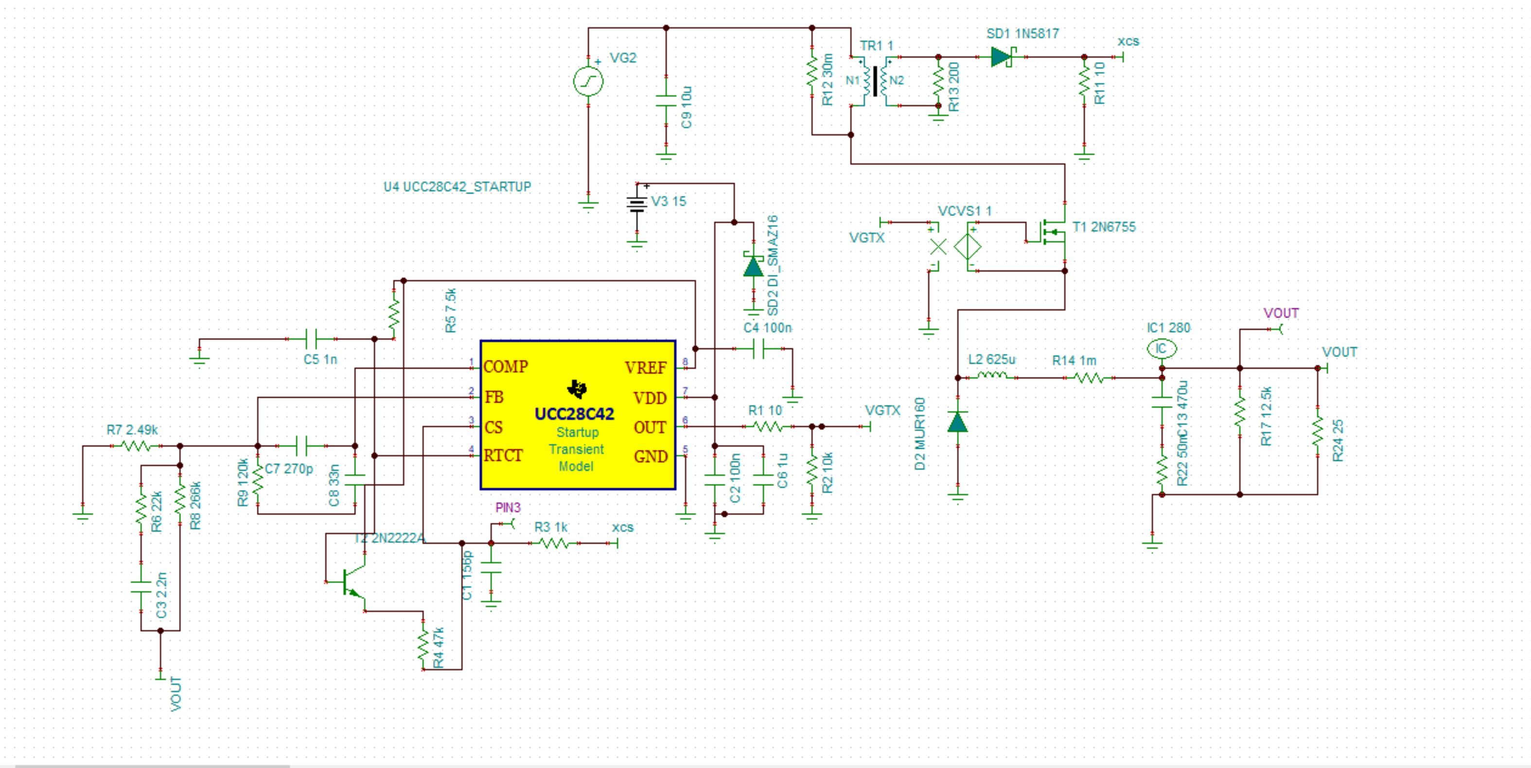
I have this circuit set up for 3kW but I just cannot stop it from subharmonic or other type oscillatory behavior. Output voltage is well controlled but suspect the current loop is not.

It has to work from min static load of 12.5k to 11 amp, 0 output capacitor added by user to 2000uF. On board load is 12.5k , on board cap is 470uF electrolytic+ 50 uF of film.

User needs max turn on time of 500usec. Well controlled transient from 0 output load to full 11 amp

Can you help me find what pole-zero locations could be wrong? The model works fine. Could it be real current xmfr is not giving enough sense amplitude? Are we adding enough slope comp & at the right place?

Would it work better is we connected the slope comp signal at the feedback node?

I added one with slope comp added to current sense. with low load-which should be without  SHO but it is not

The second with slope comp added at feedback node. with high load. It works well. Does it?

Pole-zeros were calculated from SLVA301 app note.

any help will be highly appreciated.sept12_rg10pm_comp_1diode.TSCsept12_rg10pm_slp_fdk_1diode.TSC

  • Hello Robin,
    Do you have a schematic and design specification for this application.
    Also test waveforms would be nice to view.
    A 3kW load is unusually high for a PWM controller like the UCC28C43

    Regards
    John
  • Hi John

    I had attached the TINA-TI schematic in my request. But pl see attachment again.

    3kW is not high considering output is 270V @ 12 amp with input 350V from a Weinberg 3ph PFC stage.

    But at this time, we are supplying from a  bench power supply.

    I am also attaching the most ugly Bode plot ever!

    There are two attachments here. One TINA-TI simulation schematic & the other Bode plot.

    I am afraid, the files do not seem to get "attached".

    If you still do not see them, what is the correct way of attaching a file?

    I used the paper clip icon that leads you to upload.

    robin

    sept12_rg10pm_slp_fdk_iloop.TSCAD-DC bode plot .pdf

  • John:
    Is the power level to control high because of the ratio of Vin/Vosc? What options do we have to make a buck converter just to get a better transient response ? A PFC stage wont give you a useful transient load response. So we went for a 2 stage approach.
    I attached the TI-TI schematic. The buck is built exactly as in the model. Specs are: Input: 3 ph/60 HZ, 110v , output 270V dc @12amp. Transient required is 0 to 12 amp settling in <500usec with drop no more than 3v; output capacitor at users side could be from none to 2000uF.
    For 3 ph, they have 3 single stage Weinberg converters( do not ask my why!). Its BW is <10 Hz. Its output is 350V so that components have specified NAVSEA derating.
    Seems to me I have very poor compensation. I followed SLUA 310 but not all the way. R2-C2 from that App note come out absurd. Any help will be highly appreciated.
  • Hi Robin,
    I cannot view the TINA schematic but if you take a screen shot and attach as a jpg or pdf then I will be able to open it.
    It is not advisable to run a buck converter at 270V 12A ( 3240W) because the switched currents are just too high.
    You can check this out by using the Power Stage Designer Tool.
    www.ti.com/.../powerstage-designer
    If you run this tool for your application it will give you values for the compensation components and also show you the switching waveforms.
    I think it is much easier to use than TINA.
    I recommend that you use this tool and then check a full bridge or similar type topology. These are buck derived topologies with a transformer to reduce the gain as well as for isolation.

    Regards
    John
  • John

    I appreciate very much your quick responses on this matter. At this time, we hardly have any options left other than make the buck work satisfactorily. It is a long story how small companies get into trouble through habitual  "consultants" they pour money into and get awful designs done....It is "working" largely. But we can do better in compensation & slope comp as well.

    I am helping  out a friend-owner of a company. Free.

    They are too late in the delivery. I  did not have any option to tell them " let us start from 0". Which would be a new PFC not Weinberg, That would have sufficed if done correctly no second stage would have been required.

    But let us not get into blame game.

    We are here & we got to help their customer.

    So, now: the Power bench of course wont work. I use it for simple quick solutions. (BTW, I never design without using one such tool).

    It does not come out with any solution. Duh.

    Since I do not know what limitations are in the tool, I did not try to lower down  parameters until the tool found a solution. Which would not apply to our case.

    I use quite a lot TINA-TI because of its versatility. But then you have to figure out compensation values. In this case, it is hard because TINA-TI transient model is quite insensitive to compensation vales it would seem. In this case, you have to adjust the slope compensation . The model is insensitive to a wide set of values.

    That said, I would find it helpful if you can help us determine more optimal comp & slope comp values for the model. I am sure knowing innards of it will help get optimal values wde cantest in the simulation.

    I got the comp values from SLA310 mostly. As I said before, that approach gives absurd values for R2-C2. I added Type III because the buck has to operate in transient of 0 ampto 12 amp,  It has to keep vout solid.

    Furthermore, model shows a huge startup overshoot. This is totally contained by Type III

    Will be waiting to hear what you find out. Thanks again.

  • John: Forgot to mention that Power Design tool in Java comes up with such a small screen I hardly can read it. The small window has no handles to enlarge it. It is perhaps due to Windows 10 in my laptop. Is it the same as in the TI website? WebBench is what I used instead. FYI
  • Hi Robin,

    I am using Windows 10 here and I dont have a problem.

    Afraid your small screen issue is something I cant help you with.

    Regards

    John

  • John
    I appreciate your effort in this matter. Since the response to the inputs gave " no design available", and one cannot estimate which limits on input/output are solvable, I did not try any more.
    Like I said, TINA-TI works fine. It is not sensitive to small signal conditions. And that is where I am stuck. I tried to use results from SLU301 but it gives absurd results. Yet, I can tell you this method of stepping down from Boost PFC to aircraft DClevel (270V) is very much used. Since there is no theoretical impossibility of designing such a step down buck, we are just trying to get calculated comp & slope compensation values. As such the converters works. I need to know if it is robust & if compensation values, slope compensation are adequate.
    Let me know if the screen shot of the schematics used in TINA-TI tells you anything.
    robin
  • Hi Robin,
    I will close this post since there has been no additional inputs for over 4 weeks.
    Please open a new post if you need further information.
    Regards
    John