This thread has been locked.

If you have a related question, please click the "Ask a related question" button in the top right corner. The newly created question will be automatically linked to this question.

BQ76930: Hall-Effect Current Sensor Connection - SRN or SRP

Part Number: BQ76930
Other Parts Discussed in Thread: BQ76200

Hello,

I'm planning to use a hall effect current sensor at high-side instead of shunt resistors along with a op-amp to decrease output into SRP/SRN limits of bq769x0 for current sensing.

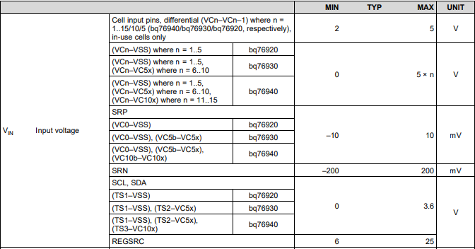
I think maximum measurable range of SRN and SRP pins of bq769x0 is 400mV, according to the datasheet.

Datasheet shows min and max typical for SRN and CCrange as -200mV, +200mV and for SRP as -10mV, +10mV.

So;

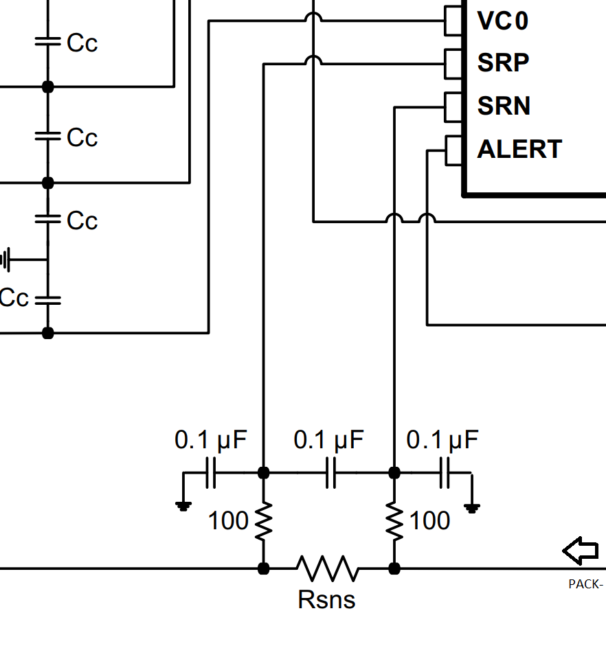
I'm planning to reduce the output of current sensor to -200, +200 range, but which pin should i connect it? SRP to ground and sensor to SRN?

Also I'm planning to use an external high-side nfet driver (bq76200) with seperate paths for charge and discharge. Should I use bidirectional sensor for charging current measurement (and reduce range to 0 - 200mV for discharge path) or ignore the charging state (SCD and OCD protections for only dishcarge i think) current sensing?

Thanks,

Oğuzhan

  • Hi Oguzhan,

    We do not have experience interfacing a hall sensor to this device, although I can see how it can provide some advantages - lower power loss and potentially improved accuracy. The connections you propose sound correct, but you will need to make sure the output of the circuit provides the expected voltage to the ADC.

    For using separate charge and discharge paths, I am attaching a document that might help highlight potential issues and provides a few suggestions. The examples are using low-side drivers, but may still apply.

    /cfs-file/__key/communityserver-discussions-components-files/196/Split_2D00_path_2D00_load_2D00_detect.pdf

    Best regards,

    Matt

  • Hello Matt,

    Thanks for the fast response and document. I think I'm going to use separate paths for discharge / charge and use the sensor on discharge path only.

    But please help me clarify a point (maybe I'm thinking fundamentally wrong);

    The datasheet shows SRN range as -200 - +200mV and SRP as -10 - +10 mV.

    Also typical applications on datasheet shows connections as:

    According to this, the voltage on SRN pin should be more close to the ground (0mV). Current goes to Rsns and this make a voltage difference (Ohm's law), so SRP should be more deviated (on the positive side I assume) compared to the ground.

    But SRP range displayed more limited on datasheet. What am I missing here?

    Regards,

    Oğuzhan

  • Hi Oğuzhan,

    The SRP pin should be connected to VSS and the voltage on the SRN pin will change depending on the magnitude and direction of the current. The SRN pin should be connected to PACK-. When there is no current flowing, these voltages will be the same.

    I think the confusion is regarding VSS. VSS is also referred to as BATT- which is different from PACK-. There is a good discussion here on this topic: e2e.ti.com/.../585790

    I hope this helps clarify.

    Best regards,
    Matt