This thread has been locked.

If you have a related question, please click the "Ask a related question" button in the top right corner. The newly created question will be automatically linked to this question.

TPS23753A: High Efficiency Reference Design for 5V 3A

Part Number: TPS23753A
Other Parts Discussed in Thread: PMP9175, UCC24630, TPS23757, TPS2372-3EVM-757, TPS23757EVM

Is there a high efficiency reference design from TI using the TPS23753A?

We want to get the maximum output power out of standard PoE - class 0/3. 

Also, we are using the Wurth transformer 749 119 350 because of height restrictions.

  • Michael, Thank you for your interest in PoE products from Texas Instruments.

    As you likely know, the transformer is one of the most critical components in driving overall system efficiency...are you open to qualifying other transformers as long as your height restrictions are met?

    Some additional questions that will help us search our library of reference designs:

    What is the maximum power level required (is it 12.95W at the load input? Class 3 maximum?)
    Is isolation required?
    What is the voltage/current requirement?
    Is there more than one output?
    Do you have an efficiency goal...or just "as high as possible?"
    I found this Wurth transformer online - it's height is 8,3mm. Is that your maximum height restriction?

    Once we have these answers, we will search our library and get back to you.
  • Michael, My apologies...I now see you have the output description in the title...5V @ 3A...is 15W...so we need to move up to Class 4, correct?

  • Thomas, thanks for your attending to my request.

    1. transformer: yes, we are open to other transformers, but we must not exceed 9mm height restriction on the PCB.

    2. Power output: yes, we need 12.95W, the class 0 or class 3 maximum.

    3. Isolation: we have a shielded RJ45 jack with GbE, so to my knowledge, yes, we need isolation.

    4. Number of outputs: we need a single output with +5V 

    5. Efficiency: no goal, as high as possible, because what we do not dissipate in the power supply is available power for the circuit.

  • Got it Michael!

    Just to be clear, you want to stay at Class 3 maximum and do not need >12.95W at the input to the design, correct?

    I ask because the title of this thread indicates the need for Class 4.
  • Hi Thomas,
    we want to stay in class 3 because customers are likely to not (yet) have class 4 PSE. So it should say in the title: 5V 2.59A
    BR
    Michael
  • Hi Michael,

    I had checked with coilcraft and wurth to see if there was a similar transformer spec as PMP9175 in an EFD15 core (much thinner) however I didn’t find one.

    For the transformer you want to use, you can get away with using it if you pair it with the UCC24630 as you suggested in our email offline. In this case you can use the TPS23753A.
    Or you can use it in a driven flyback approach (with an external gave drive transformer). In this case, you can consider the TPS23757 since it has a second gate drive. Its EVM has pretty good efficiency for the DCDC converter (~91-92% efficiency) and uses an EFD core.

    www.ti.com/.../slvu318b.pdf

    Regards,
    Darwin

  • Hi Darwin,

    thanks for your answer. Do you have a reference schematic for the UCC24630 replacing D3 in slvu315a or a similar EVM?

    BR

    Michael

  • Hi Michael,

    Unfortunately, we have yet to use this synch gate controller in our TI designs or EVMs for PoE. I've seen it used mostly in offline applications at greater than 30W converters and not yet for 13W. It may be difficult to modify an PoE EVM with this controller as well. It might be that you must prototype it first with a new board.

    How about the TPS23757 board I recommended? It would be higher efficiency performance than using UCC24630 since TPS23757 design is a driven approach.

  • Hi Darwin,
    thanks for your continued support. I did consider the TPS23757 design but was shying away from the gate drive transformer for cost and space reasons. Would you consider combining the SLVU318B with the FDMQ8205A FET bridge or is the figure of ~91-92% efficiency already obtained with the standard Schottky bridge?
  • Hi Michael,

    The 91-92% was the DCDC converter efficiency only. So a schottky bridge will drop it down to ~88-89% for the PD system. With the FDMQ part, it'll probably be closer to 90-91% for the PD system.
  • Hi Darwin,

    I have 2 last questions, before we close this thread:

    1. There are 1 or 2 (in case of aux power) diodes B1100 in the power flow. This causes app. 0.2W of loss for each diode, i.e. 0.4W in case of aux power. Is there a better way?

    2. Would you be willing to do a design review of our schematic in order to spot any mistakes?

    BR

    Michael

  • Hi Michael,

    1. Yes we have an in-between bridge (FET-diode bridge) that is not as bad as a diode bridge but not as good as a FET bridge. Please see the bridge we use in TPS2372-3EVM-757. For this design, note the det resistor on the EVM. Be sure it is increased when using this bridge.

    2. Absolutely! Let us know and we can check it.

    Thanks!

    Regards,

    Darwin

  • Hi Darwin,

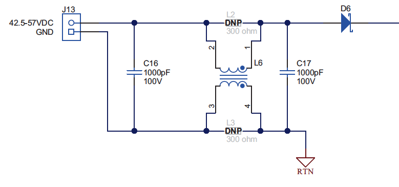
    to 1) I was not referring to the bridges but to the polarity protection diodes like D6 in the adapter power path:

    Do you have something more efficient than the Schottky diode?

    BR

    Michael

  • Hi Michael,

    Ah I see what you're asking now. Yes I have seen designs in the past that use a PFET as the pass element instead of the diode and a divider from the input to the gate. I have not tried this myself though.

    Regards,

    Darwin

  • Hi Darwin,

    do you have a sample schematic and part recommendation for such a PFET ORing diode?

    Best regards,

    Michael

  • Hi Darwin,

    I have followed you recommendation and used EVM slvu318b in our design. Could you please check my schematics for correctness? According to the documentation this design delivers 11W. Other products, like the Silvertel Ag92015-S (www.silvertel.com/.../160-ag9200.html), advertise their modules as being able to deliver 13W with standard bridges. What makes the difference of 2 Watts?

    Best regards,

    Michael

    Adatis tps235757 5V 2.2A for review.pdf

  • Hi Michael,

    Sure I can take a look at the schematic and let you know.

    A converter can be designed for 13W output power but per the PoE standard (IEEE802.3at), a Type 1 PD’s max input power is 13W. This means given the system efficiency (bridge, converter efficiency), the output power of the converter can never be 13W. So if the load actually pulls 13W at the output of the converter, the input power will exceed the max IEEE spec and it can be considered non-compliant. This is why we put 11W on the EVM, because the total system efficiency is ~86% and it meets the 13W max spec.

    Now, if you use a FET bridge, you can get closer to 12W at the output of the converter to meet the IEEE spec.
  • Hi Darwin,

    the TPS23757EVM uses the Pulse PA0184 gate drive transformer. This transformer is rather large. Can we replace it with B82804A0354A110 ( en.tdk-electronics.tdk.com/.../b82804a.pdf ). I suppose it has similar parameters, but a bit smaller that current transformer.

    Best regards,

    Michael

  • Hi Michael,

    Closing this thread now since we found a working solution. Thanks!