This thread has been locked.

If you have a related question, please click the "Ask a related question" button in the top right corner. The newly created question will be automatically linked to this question.

BQ78350-R1: Part has a short circuit from VCC to Ground

Part Number: BQ78350-R1
Other Parts Discussed in Thread: BQ78350, BQ76930, , BQ76200

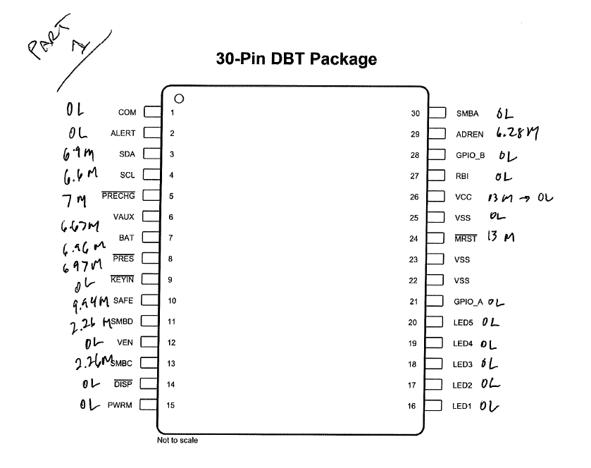
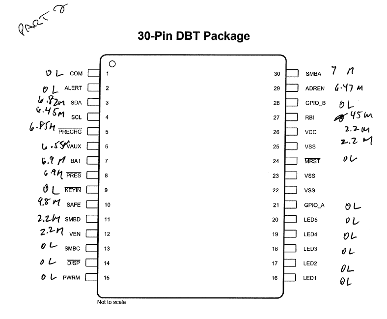
I wrote a post yesterday on this component, but it must not have saved because I cannot find it today.  I have implemented a demo design utilizing the BQ78350-R1 paired with the BQ76930.  During initial power up/testing, we are finding a short circuit between the REGOUT (2.5V) regulator and ground.  Upon investigation, this short circuit (<5 ohms) went away after removing the BQ78350.  I have had this happen on 4 or 5 PCBAs, a couple of them I didn't even finish building the packs because I noticed a couple of circuits getting hot with the power draw trying to feed the short circuit.  There is one pack that we were able to communicate with for a little while, but now that is not operational and the same rail is shorted.

Any ideas on where to start investigating what can be causing this damage to the BQ78350 device?  Additionally, I have a separate 3.3V regulator on the output of the FETs that is also seeing a short circuit on the same boards, still unsure how that is happening as well.

Thanks, Mike 

  • Hi Mike,

    Can you tell me the full part number for the BQ76930 device you are using? The device has versions for both a 3.3V REGOUT and a 2.5V REGOUT. If the 3.3V version is used, it can damage the BQ78350 because the voltage exceeds the abs. max.

    Thanks,
    Matt
  • Hi Matt,

    The full part number is BQ7693001DBT, I have confirmed that the boards built are marked with "BQ7693001".

    Thanks, Mike
  • Thanks for confirming Mike. Can you share this portion of your schematic and we can review to see if we can identify any potential issues?
  • Matt Do you have an email I can send this to? Mike
  • Yes, I sent you a private message.
  • Thanks for sending the schematic Mike. I looked over it and I don't see any problems. I'll ask my colleague to take a look as well and I will let you know if he finds anything or has seen a similar issue in the past.

    Regarding the other observation you mentioned, is the 3.3V regulator output shorting to ground and is it being used as the pullup voltage for the SMBUS? Are you able to tell which pins of the BQ78350 device are showing low impedance to see possible sources of electrical stress?

    Thanks,
    Matt
  • Matt

    Yeah take a look and let me know, I’m a bit baffled here. Yes the 3.3V pulls up the SMBC and SMBD lines with 10k that connect to our MCU. I have removed parts, I’ll take a look at what pins have the short.

    Thanks, Mike
  • Hi Mike,

    Is the SMBUS or the 3.3V regulator referenced to PACK-? Is there ESD protection on the SMBUS lines?

    Thanks,
    Matt
  • Hi Matt,

    I just sent you the full schematic, I had left out the pages that weren't really relevant to your components in the design. To answer your questions:

    I have labeled the grounds like this (similiar to your reference designs). Where the bottom of the stack comes in, I have labeled Batt-, and it is tied to GND through the net tie (to segregate the high and low current paths). On the other side of the sense resistor, Pack -, I have labeled DGND. That being said, the 3.3V rail is referenced to DGND (Pack -). There is no ESD protection any those SMBus lines, as they only go between my MCU (Renesas) and the BQ78350-R1, they aren't in contact with anything external. I have separate SMBus lines that do go to the outside world, but they are a separate channel off of my MCU.

    Thanks,
    Mike
  • Hi Mike,

    I'm wondering what might happen during a fault detection event where the low-side FETs are opened. It seems that there is potential for damage or at least lost communication. I'll look at this more tomorrow, but take a look at this older thread to see what I mean. (e2e.ti.com/.../2387852)

    Thanks,
    Matt
  • Hi Matt

    That link isn't working for me.

    Mike

  • Sorry about that Mike. I accidentally added an extra character tot he link address. Let me try again: e2e.ti.com/.../2387852

    Matt
  • Matt

    On 9/20 you asked me if I can tell if any of the pins themselves are shorted.  I have removed 2 parts, and measured all pins referencing pins 23&24 (purposely shorted these VSS pins together).  See images below, but I'm not seeing any short circuits externally like this.  On one of them, VCC was jumping around between ~13M and OL, could be just a bad connection because on the other one it was about 2M.

    I'll review the link you sent me today.  Any more luck on your end?

    Thanks, Mike

  • Matt,

    Have you had any more luck with this on your side?

    Thanks, Mike
  • Hi Mike,

    The link to the older thread is what we think is most likely the issue. I looked at your resistance measurements, and I'm not sure what to think. It doesn't appear you observed any low impedance paths. Is it possible that by removing the BQ78350 from the board, you are breaking a low impedance path related to the damaged 3.3V regulator?

    Matt

  • Matt,

    I believe we figured out what our problem was.  Our 3.3V regulator that was referenced to the switched ground is a switching power supply.  If you remove its ground, there is no way of knowing what it is going to try to regulate to, I'd assume whatever the ground floats to it'll try to regulate from that.  In investigating my 3.3V short after removing the BQ78350, I found various devices powered from that part to be shorted out.  How that damaged the BQ78350, I can only assume that it pulled up those SMBus lines to a voltage greater than what the part can handle.  Does that make sense?

    That being said, do you have any circuit examples or guidelines for changing our design to use high side fets?

    Thanks for all of the help,

    Mike 

  • Hi Mike,

    I apologize for the late reply - I was out of office for a couple of days last week. I think you're right - the BQ78350 must have been getting damaged through the SMBus lines.

    There is a good app note on using the BQ76200 high-side FET driver to help you get starting on the design change. Here is the link to the product folder where you can see the datasheet and technical documents: www.ti.com/.../technicaldocuments
    And here is the best app note to start with: www.ti.com/.../slua794.pdf

    Best regards,
    Mat