This thread has been locked.

If you have a related question, please click the "Ask a related question" button in the top right corner. The newly created question will be automatically linked to this question.

UCD9090: i2c/PMBus programming

Part Number: UCD9090


Hi

i'm trying to program UNC9090 device for prominent customers. According to i2c/PMBus interface specification i send address of device and command (f.e. to get ID i send 0x68 and 0xfd ). But whatever i do i get ACK for address and NACK for command. If i change resistors and therefor address, the device sends NACK to old address and ACK to new one. So device "understands" me. I have changed the frequency, gaps between the frames. The same result. 

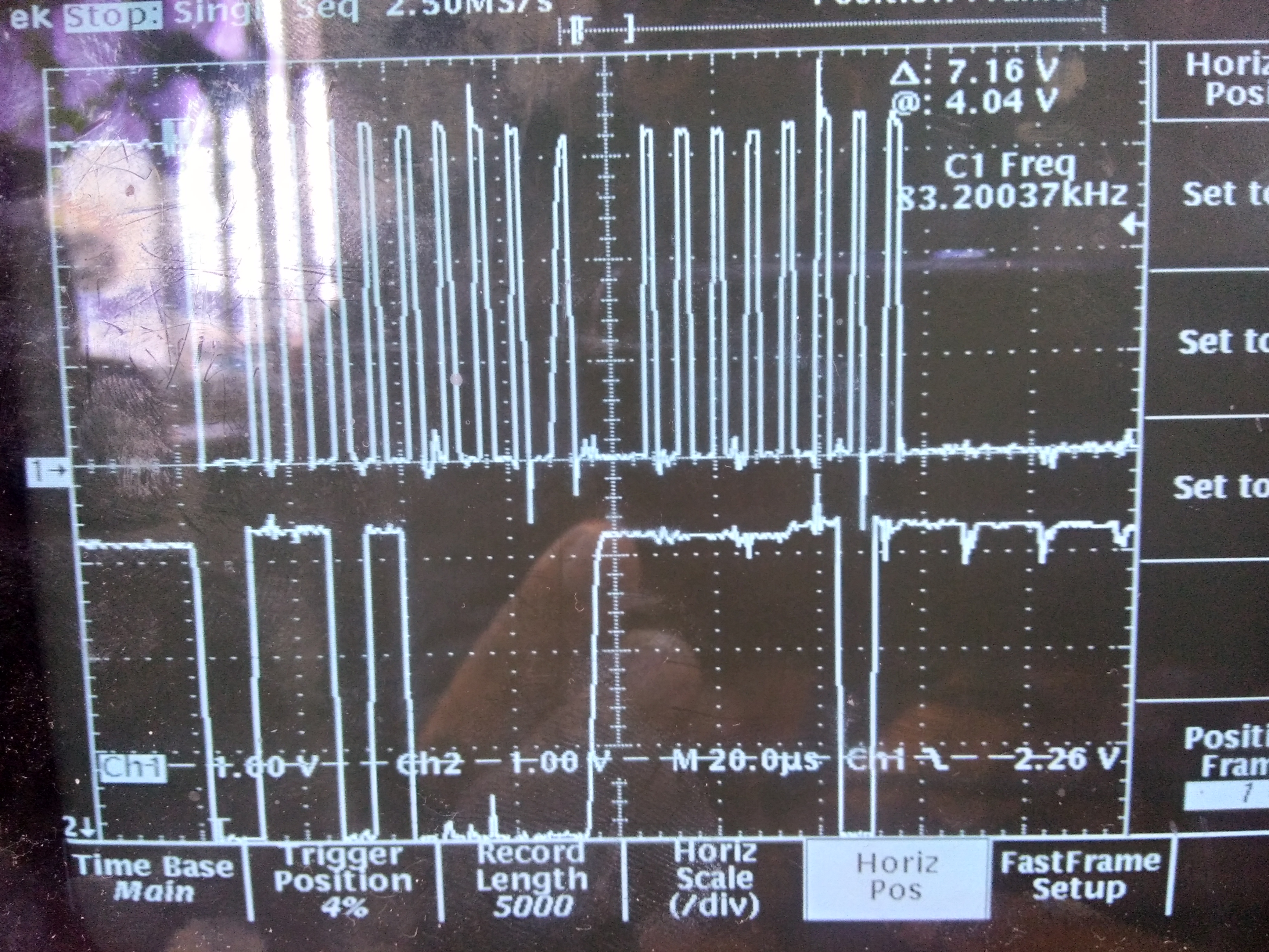
i also noticed some strange thing. If i set PMBus_CLK to input during response (ACK/NACK) from device, then sometimes i lose 9th clock fro command frame (address frame is OK).

Have you any advice? 

Thank you very much.

  • Do your i2c host support clock stretching? UCD9090 need clock stretching to work.  Do you have UCD90SEQ48EVM? if so, you can compare the waveform?

    Regards

    Yihe 

  • Yihe,

    Thank you for your reply. 

    Yes, host support the clock stretching, but whats happening is the following, once i see the slave is holding clock low i'm waiting until it goes high and check response. And in-first, the waiting-time is abnormal huge( freq = 3kHz, waiting-time = 100ms), in-second, i get NACK after that waiting and what do i have to do afterward? Changing the frequency do not produce results.

    No, i haven't UCD90SEQ48EVM. It would be highly appreciated if you attach waveform. I do hope i'm not bothering you.

    Dmitry

    Thank you

  • Could you capturet the waveform with scope instead of logic analyzer? this will help.

    as i2c host is required to read back the clock signal after releasing it to the high state and wait until the line has actually gone high. once it goes high, the host shall continue the clock pulse. i can not believe that i2c is low at 100ms.

    Please refer the waveform capture from EVM with 400KHz clock. you can see the clock streching after 0xFD is received.

  • Yihe 

    Thank you so much for your help.

    I waste all day yesterday. My waveform is attached. Still cannot get second ACK. The device release clock after huge (about 100 ms and more) time and with NACK. Seems i have waveform like you have sent to me, but....I can guess problem with rising power. May be i must use a curtain frequency. Or time intervals between power-rising and i2c-start? Or some other restrictions?

    I'm so sorry to disturb you but may be this waveform will give you any information whats wrong

    I noticed that waveform is heavily dependent on delay after power is on

    Dmitry

  • you are running at 100KHz. what's your pull-up resistor?
    100ms is defnitley wrong since this violates PMBus spec. the bus shall not be hold low more than 35ms.
    What did you mean the waveform is heavly dependent on delay after power-on? how soon did you start send the command after the 3.3V is stable?
    Is the UCD9090 working relaible in your setup? Do you have other i2c master tool to try? maybe try to order www.ti.com/.../usb-to-gpio, this is a approved solution to support UCD9090.
    Regards
    Yihe
  • Yihe
    I almost got the divice!!! ....but...
    I have changed the capacitors on the BPCAP (4.7u || 0.01u), added 4.7u || 0.1 on V33A and 4.7u || 0.1 on V33D and i got new result. Now i have ACK on address, ACK on 0xFD (!!!) but then i'm trying to get the ID i receive 0xff ( nonsense )
    So, i send 0x68 (address), 0xfd (command), trying to get the result. Righty?
    I have frequency 250 kHz
    I have voltage on BPCAP about 1.7V. Is it acceptable? Should it be 1.8V exactly?

    What do you mean "Is the UCD9090 working relaible in your setup?" How can i tell that?
    I have not another tool. My tool is a programmer i'm programming to read/write your device.
    You were a great help. Thank you so much
  • Thanks for the updates. please follow UCD90xxx Schematic guideline at www.ti.com/.../slvub50 to make sure the power section is deisgned correctly.
    0xff is no right which means that nobody drive the bus and it is pull-up high by default.

    Regards
    Yihe