This thread has been locked.

If you have a related question, please click the "Ask a related question" button in the top right corner. The newly created question will be automatically linked to this question.

Compiler/UCD3138: UCD3138

Part Number: UCD3138

Tool/software: TI C/C++ Compiler

Hi:

I want to ask some quentions about UCD3138 DPWM master-slave mode.

Suppose LLC topology. I configure DPWM0(Primary mos) as master, and DPWM1(SR mos) as slave.

then i will write code like this:

"

Dpwm0Regs.DPWMCTRL0.bit.MSYNC_SLAVE_EN =0;
LoopMuxRegs.DPWMMUX.bit.DPWM0_SYNC_SEL = 0;

Dpwm1Regs.DPWMCTRL0.bit.MSYNC_SLAVE_EN =1;

LoopMuxRegs.DPWMMUX.bit.DPWM1_SYNC_SEL = 0;

"

and I suppose DPWM0 's deadtime is the same as DPWM1's deadtime, for example: DPWM0's deadtime is 350ns , DPWM1‘s deadtime is 350ns

and filter0  is connect to both dpwm0 and dpwm1.

Do DPWM1 follow DPWM0 no matter what circumstances?

if both EVENT1 is same .   They will always open together ,but dpwm1 will close earlier than dpwm0 or the same time as dpwm0 (According to the resonance frequency), Do I understand correctly?

Is there any situation that is not open at the same time(Even the phase will stagger.)? 

many thanks!

Zoe

  • an expert will help you soon
  • Hello Zoe
    If DPWM0 is configured as the master and DPWM1 the slave, and the value in the register Dpwm0Regs.DPWMPHASETRIG.all = 0, and the same filter is driving the two DPWMs (and the two DPWMs are configured identically), then DPWM1 should be an exact copy of DPWM0.
    Does this answer your question?
    best regards
    Cormac
  • Hi Cormac:

    Thanks very much for your answer!

    I did everything you said. except DPWMPHASETRIG。

    if Dpwm0Regs.DPWMPHASETRIG.all = 2, what will happen?

    now,we have an situation that sometimes DPWM1is open earlier than DPWM0,sometimes the two DPWMs has phase difference. I have no idea that why this happen.

    Hope you can help me.

    Thanks a lot!

  • hello Zoe
    With Dpwm0Regs.DPWMPHASETRIG.all = 2, DPWM1 should lag DPWM0 by 8ns.
    It sounds like the phase difference between them can be different on your system.
    Could you re-try with Dpwm0Regs.DPWMPHASETRIG.all = 0?
    Could you send on the details of your DPWM0, DPWM1, loop mux, filter and front end initialization after power on / reset?

    After a power on / reset of the UCD, do you find that when DPWM0 and DPWM1 start switching, that the phase difference is always the same, and that the inconsistency in phase difference occurs when the DPWMs are shut off and restart (say due to a fault?). If this is the case, could you also send on details of how you are re-configuring these peripherals after the power supply shuts down and restarts?

    Best regards
    Cormac
  • Hi Cormac:


    Thanks for your timely reply!
    when a power on/reset, I have configured the DPWM0,DPWM1,LOOP MUX,FILTER AND FE.(Refer to TI's code)in main.c:
    //Initialize DPWMs
    init_dpwms();
    //Initialize sample trigger location
    /*It is crucial that when specifying the EADC sample trigger location;
    that it is always in a location valid to all operating modes.
    In general it should be placed somewhere between the beginning
    of the DPWM period and EVENT4 - 500 ns.*/
    init_sample_trigger();
    //Initialize LOOPMUX
    init_loop_mux();
    //Initialize FRONTEND0 for voltage controlled feedback
    init_front_end0();
    //Initialize FRONTEND1 for current controlled feedback
    init_front_end1();
    //Initialize FRONTEND2 to continuously sample IPS and implement ZCS avoidance function to prevent Qtop turn on into Qbot body diode conduction.
    init_front_end2(); //ZCS feature
    //Initialize PID Filters
    init_filter0();
    init_filter1();
    init_filter2();


    when a fault occured, first go to state_fault,then when PSON change, will go to transition_to_idle_state, in this state, I will clear all fault and
    global_disable();
    global_enable();
    I think this two codes will make DPWM0 and DPWM1 have same phase ,Do I understand right?

    I didn't re-configruing the DPWM0,DPWM1,LOOP MUX,FILTER AND FE.
    for example: init_dpwms(); and so on.
    Is there any problem?

    If DPWM0 is small to zero, Can DPWM1 still follow the phase of DPWM0?
    Is there any literature showing the mechanism of synchronization?


    Hope your reply!
    Zoe
  • Hi Zoe

    From examination of the code you provided and the LLC EVM code, I can't see anything obvious that could be causing your issue.

    It seems that you are following our LLC EVM code quite closely. Is it half-bridge LLC?

    It would be helpful if you can provide more information, as to be honest I still don't have a good handle on what you are seeing. Could you describe in more detail the issue, and any pattern that you observe that causes it to occur? Does it only occur after the power supply restarts, after a shutdown due to a fault? If so, is it a particular fault, or any fault? 

    The only thing I can think of is that the DPWM counters are not getting reset correctly after a fault causes the DPWMs to stop. Could you try commenting out the first two lines below from function clear_faults() in standard_interrupt.c, as I have done below

    // global_disable();  
    // global_enable();

    FAULTMUXINTSTAT_value = FaultMuxRegs.FAULTMUXINTSTAT.all;

    This will leave the two DPWMs enabled permanently, which should be okay, as you are calling gpio_dpwm_off() beforehand, which disconnects the DPWM modules internally from the DPWM pins.

    If this doesn't work, could you change the code in clear_faults() to what I have shown below, and re-try

    global_disable();  

    Dpwm0Regs.DPWMCTRL0.bit.PWM_EN = 0;  // disable DPWM0 locally

    Dpwm1Regs.DPWMCTRL0.bit.PWM_EN = 0; // disable DPWM1 locally

    Dpwm0Regs.DPWMCTRL0.bit.PWM_EN = 1; // enable DPWM0 locally

    Dpwm1Regs.DPWMCTRL0.bit.PWM_EN = 1; // enable DPWM1 locally

    global_enable();

    FAULTMUXINTSTAT_value = FaultMuxRegs.FAULTMUXINTSTAT.all;

    If neither of these suggestions changes anything, let me know, I will re-assign this post to another member of our team who is more familiar with the LLC firmware and EVM.

    Best Regards

    Cormac

  • HI Cormac

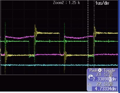
    Sorry to bother you again.Please help me to look at this picture.

    yellow: DPWM0A Vgs (master)

    pink:    DPWM0A Vds (master)

    green: DPWM1A Vgs (SR)

    The two signals DPWM0 A and DPWM1A  should be opened at the same time,and closed at the same time.

    Why DPWM1 looks like open all the period?

    It happened by accident.not always.

    Please help me, and let me know what information you need.or what suggestions you have?

    Thanks a lot

    Best Wish

    Zoe

  • Hi Zoe

    Yes, the green trace doesn't look correct.

    It seems like you are getting some kind of pulse extension.

    It looks like you are in resonant mode (and not PWM mode) when this occurs, can you confirm this? Or does it perhaps occur when transitioning between PWM and resonant mode?

    Is this load dependent? What load level is this issue occurring at?

    Could you send on a "normal" waveform, where the green and yellow are in concert?

    Could you send on your register configuration for the filter you are using and for DPWM0 and DPWM1 please?

    Best Regards

    Cormac

  • hello Zoe

    We haven't heard from you in a while, has this issue been resolved? 

    Kind Regards

    Cormac