This thread has been locked.

If you have a related question, please click the "Ask a related question" button in the top right corner. The newly created question will be automatically linked to this question.

TPS62135: Unexpected behavior at output.

Part Number: TPS62135

Hi!

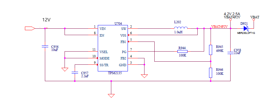
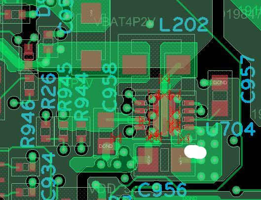
Attached is a design,layout and schematics of a buck converter(TPS62135) whose output is 4.2V (for input voltage of 12V). We used the same capacitors and resistors suggested by wbench design attached below. The only changes were that the 499K resistor was of 499K 1/16 W, 0402 package (but in the next design we will use a 1/5W resistor of the same package). We get 11.8V at the output, way above the desired value (which is 4.2V). We are clueless as to what is causing this rise in output volage. Also the attached design worked for us intially but failed later on. Can you please go through and help us out. Thanks in advance.

webench_design_5634417_7_94384900.pdf

  • Hi Nithish,

    Have you confirmed that R945 and R496 are installed correctly and not mixed up (swapped for example)?

    You can look at Vin, Vout, SW, and FB to see what the IC is trying to do.
  • Hi!
    we checked R945 and R946. Both are installed correctly. Also Vin is 12V , Vout 11.96V, SW 11.96V and voltage at feedback pin varies starting from 0.8V and stabilizes to 1.9V . We have used a 1/16 watt (62.5mW) 0402 resistor for R945, in contrast to webench designer's suggestion to use a 125mW resistor. Will it affect the feedback voltage? We notice that once we power on the device, feedback voltage is 1.2V and then it keeps on increasing and then stabilizes at 1.92V.
  • Thanks for confirming. Did you look at each of those signals with a scope to see if there is any AC content?

    If they are really at those DC voltages, you likely have another voltage in the system which is appearing on the output, as described here: www.ti.com/.../slyt689.pdf
  • Thanks for the reply. we will go through the document. can you please clarify if the resistor (R945, mentioned above) is causing a problem since we chose one of a lower wattage. Also, earlier we made a few boards with the above circuitry and it worked fine, but while troubleshooting, we touched the IC surface and then the regulator stopped giving output in the older boards as well. Is this regulator ESD sensitive ? also all the capacitors that we have chosen is rated 50V while the webench design suggests different voltages for each of the capacitors. Does the voltage rating cause a problem?
  • You can easily calculate the power loss in the resistors by using V^2/R.

    Yes, all semiconductors are ESD sensitive. If other boards are working, then you probably damaged something and should replace it.

    The voltage rating of the caps is not critical, but rather their effective capacitance in your circuit. This should be above what is required in the D/S.
  • HI!
    We replaced a regulator for one of the defective boards, but this time taking care not to touch the surface of the IC or its neighbourhood. The output we get is approximately 4.18V as expected. Earlier, we checked the connections and voltages and everything seemed alright. We think it is ESD that caused the problem as you mentioned above. Thanks for the help!