This thread has been locked.

If you have a related question, please click the "Ask a related question" button in the top right corner. The newly created question will be automatically linked to this question.

UCC28951-Q1: UCC28951-Q1

Part Number: UCC28951-Q1

Hello Sir

I'm designing the dc dc converter for battery charger application using controller ic UCC28951-Q1.

My design specifications as follows 

power rating of converter 1320W

Vin: 310-410Vdc

Vout: 13.2V,100A.

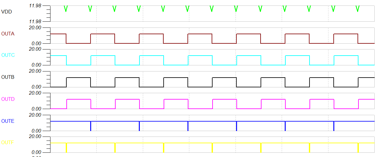
Now i want to test only control circuit whether I'm getting the required gate pulses or not.

Below I'm attaching the control circuit

Control circuit.pdf

In the power circuit, I'm using hall effect current sensor and there it is amplified by opamp and given it to the CS pin through the low pass filter and applied voltage to cs pin is 2V because it will trip at that voltage.

Below is the simulation circuit implemented in TI and the pulses obtained from simulation.

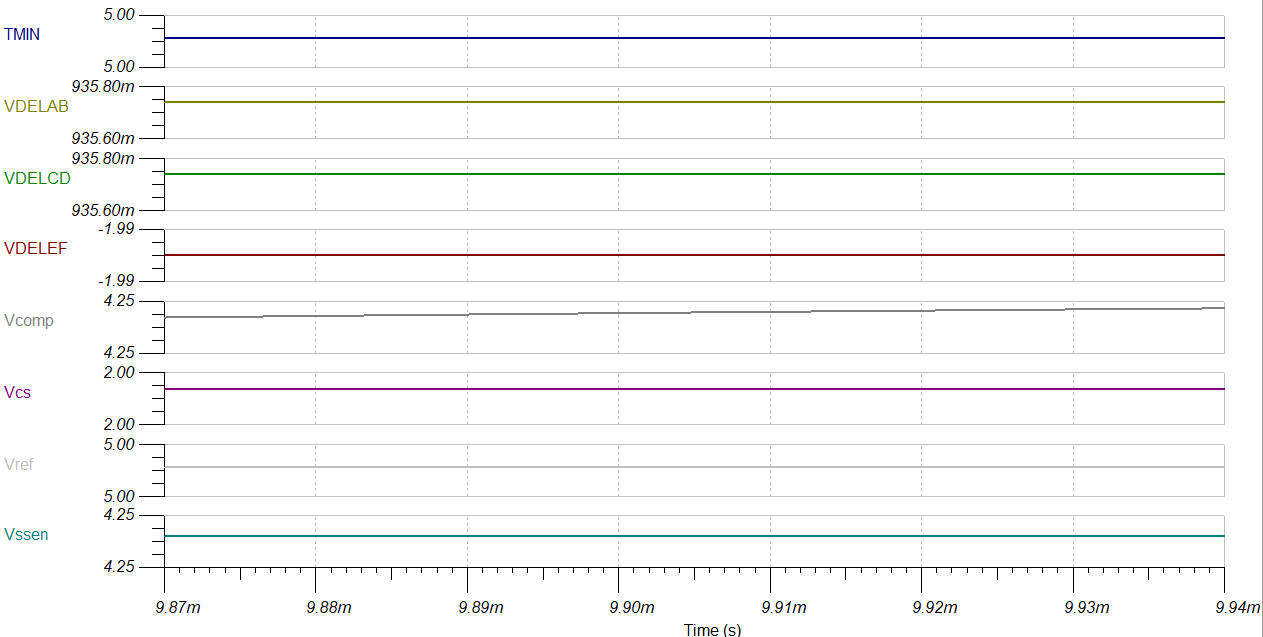
I have provided 2V constantly to the CS pin.In practical it may vary. Should i give triangular waveform to the CS pin or how to test ?

and Vout is 13.2V which is the output of the converter given through the resistor divider to EA-. At that instant there are no output pulses .when I change Vout to below 12.9V ,there are output pulses.

Why it is happening so?

And if there are any corrections in the circuit please help me to modify any.

At the end please help me in testing the controller alone , what are the input requirements to that IC or will it possible to test the circuit alone without the power circuit ?

Thanks

Regards

Rajashekar

  • i have obtained those pulses at Vout=12.9V
  • Hello Rajashekar

    In your sim results you can see that COMP is saturated high at about 4.25V. The PWM comparator should trip when the CS signal plus slope compensation reaches 4.25V - 850mV offset (The offset is not shown explicitly in the block diagram but you can see it in Fig 36). Of course what willhappen is that the Cycle-by-cycle (CbC) comparator will trip first when CS reaches 2V and this will initiate a hiccup behaviour as shown in fig 42.

    You are feeding a constant 2V onto the CS pin and the slope compensation ramp is added to this before the signal goes into the PWM and CbC comparators.

    You should monitor the SS/EN pin and compare it to Fig 42 to see what state your system is in.

    What to do next ?
    Putting a fixed 2V voltage on CS is unrealistic - you really need to find a way to simulate the current ramp and feed that into the pin. As a first step you could OR OUTA and OUTB and tie a RC to its output. This will give you a ramp and you can adjust the RC values so that at the end of a Dmax on time (5us at 100kHz) it reaches about 1V. There is an internal pull down on the CS pin which activates when the PWM or CbC comparators trip - in the real world this 'resets' the CS signal back to 0V in readyness for the next cycle. I'm not sure if this behaviour is included in the model so you may have to add some additional circuits to do it.

    The other problem is that the COMP signal is locked high. This is the output of the error amplifier so it's difficult to control. Try configuring the error amplifier as a unity gain buffer (IN- tied to COMP) and then put a DC voltage on IN-. This DC voltage would be fed directly into the PWM comparator + input and adjusting it should allow you to change the duty cycle. I'd start with about 500mV just to get started.

    It should be relatively easy to get the sim to run with the changes above but you would have to manually control the CS ramp amplitude and the EA- voltage so that they mimic the behaviour of a realistic power stage. You might want to use a piecewise linear voltage source to put a varying voltage on EA-. It can be done of course and will give you some experience of how to run the model but it might be better in the longer term to add a power stage, especially if you want to close the feedback loop and use the error amplifier 'properly' and not just as a unity gain buffer. You can always just add voltage controlled switches for the MOSFETS to simplify the sim.

    Hope this helps
    Please let me know if you have any further questions.

    Regards
    Colin