This thread has been locked.

If you have a related question, please click the "Ask a related question" button in the top right corner. The newly created question will be automatically linked to this question.

LM3489: Sealed Lead Acid Charger Oscillates at ~5MHz during all off-cycles

Part Number: LM3489
Other Parts Discussed in Thread: LM25085

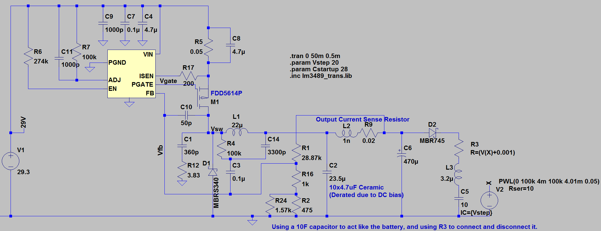
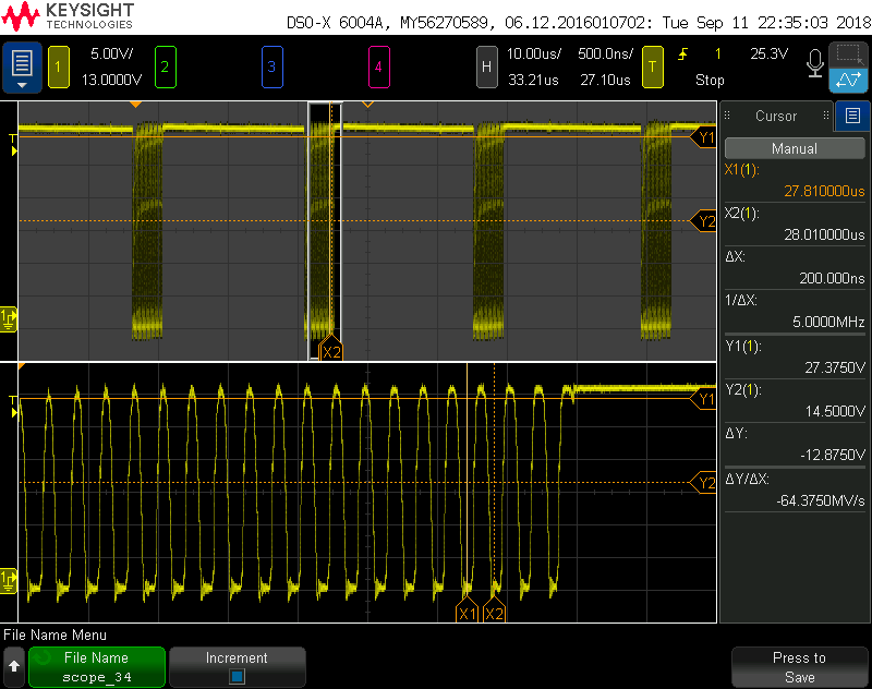
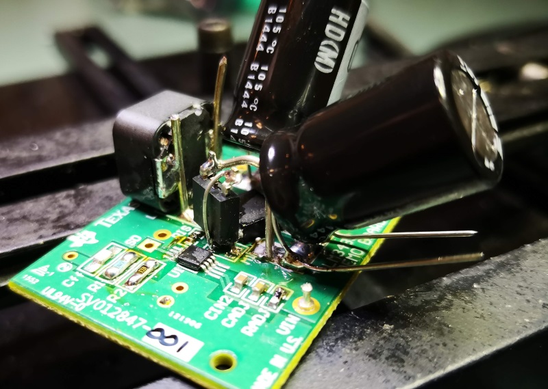
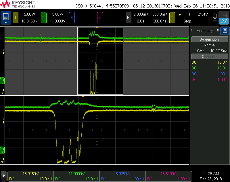
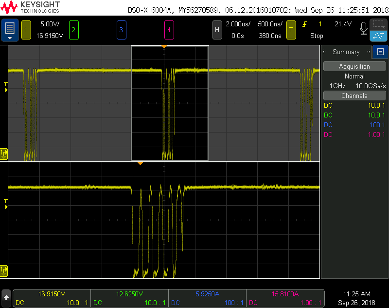
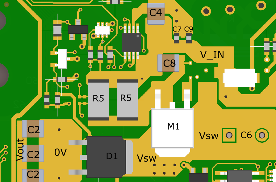
Shown above is a 4.2A SLA charger circuit with external 4.2A current limit circuit removed because the issue happens with that circuit removed. The circuit performs well, meeting its desired output voltage, current, and dominant switching frequency. The problem is that during the 'off time' of each switching cycle the controller is oscillating at ~5MHz instead of turning the FET off. The gate driver inside the LM3489 is somewhat weak and during this time the FET goes linear and dissipates so much heat that it exceeds its junction rating. I have not found any way to stop this from oscillating, below is a list of some of the changes I've tried (one at a time):

  • Removed the 470uF electrolytic to increase the ripple voltage
  • Remove the ceramic capacitor bank and rely on the electrolytic (because the ceramic capacitors have an SRF of about 3MHz)
  • Replace the C3/R4/C14 ripple network with just a feed forward capacitor
  • Connect that feed forward capacitor after the 20mOhm sense resistor
  • Feed forward capacitance values tested range from 100pF through 1uF
  • Attempted to reduce the switching node slew rate by:
    • Increasing the snubber all the way to 0.1uF/0ohm
    • Using a FET with a much larger Qg
    • Putting a capacitor in parallel with the FET gate
  • Lifted the FB pin and wired a very short and direct feedback network
  • Modified the LM3489 Eval board with my components

Despite all of those attempted changes, the part still oscillates during the off-cycles. I am out of things to try. How can I get this to stop oscillating?

  • I forgot to mention, the 50pF capacitor in the spice model is a reliable way to simulate the oscillation and is not part of the design. Unfortunately, changes to the spice model that fix the oscillation do not work in the real world.
  • I would try to put a 10 to 100 Ohm resistor in series with the gate of the FET.
  • Didn't work, I tried both 10ohms and 100ohms. 

  • If it got better you might try some other values.
  • That didn't improve the problem, it is actually just holding the FET linear through most of the off cycle. What's notable is that shortly after the switching node reaches ground, when no part of the system is changing states, the FET is getting turned on. Shown below with 250ohms:

  • Yes; that is why I was thinking that the FET/drive combination is oscillating. Could you try a FET with different capacitance ?
    It looks like you have good input bypassing. Are C7, C4, and C9 close to the VIN and GND pins??
    Also is the FET gate close to the IC ??
    You have a very large value of C8 across the sense R; I would try to remove that and see what happens.
    Also, you can try to increase the value of C11.
    Also, be sure that your layout is close to that recommended in the data sheet.
    You could also get a EVM for this device from TI and start with a known good design and modify to what you need.
  • As I said in my first post, I have already tried a FET with a much larger Qg and I also put a capacitor in parallel with the gate to drive the capacitance even higher. I also said in my first post that I already modified the EVM with my own components and it still oscillated, I even put a picture of that board showing my best effort at fitting my larger components on such a small board.

    This design started as an LM25085 design that had an issue with the gate drive current triggering the overcurrent protection, C8 was used to bypass the fast gate drive transients around the sense resistor. Removing it did not change the oscillation.

    I have not tried changing the value of C11 yet.

  • I would try a FET with lower capacitance; I think there is a limit stated in the data sheet.
    You could try to get C7 and C9 closer to the VIN and GND. And maybe get the gate of M1 closer to the IC.
  • The FET I started with was the FDD5614P (Qg=15nC @ 10V), the best I could find was the STD10P6F6 with Qg=6.4 @ 10V before the Rdson would get too high. This improved the oscillation but did not make it stop.

    I can't move M1 any closer without re-laying out the board, and at this point if I'm going to change the layout without knowing that it fixes the issue I'm going to change to a constant frequency converter like the LTC3824 and avoid the issue altogether. 

    STD10PF6F6 (2.5x less Qg) with C7 and C9 moved directly onto the IC pins:

    And I also added another 4.7uF ceramic capacitor across the pins, still didn't address the issue:

  • Daniel,

    Your schematic has R5 for current sensing but the datasheet recommends connecting the ISEN resistor (R17) directly to the drain of the PFET. Have you tried connecting R17 to Vsw as opposed to the source of the PFET?

    -Sam
  • Hi Sam,

    Thanks for looking at this. I tried changing R17 to 0ohm and it did not stop the oscillation. I have not tried using Rds_on current sensing because I am following the recommended setup in Figure 23 for using a designated resistor (although you were right and R17 was only for Rds_on sensing).

    One observation I've made: If I change R7 to be much lower than required and I use a resistive load on the output such that the converter still makes the desired output voltage and current the oscillation is gone. In other words the fixed overcurrent one-shot off-time is not susceptible to this oscillation issue.
  • Daniel,

    Interesting. Thanks for continuing testing and sharing your findings.

    I just noticed C10. That will pull FB low every time SW goes low which may trick the part to turning back on immediately (after Ton_min which is 100ns which is what we're seeing in your waveform). Try removing C10 and testing again.

    -Sam

  • Hey Sam,

    As I said in my second reply: "I forgot to mention, the 50pF capacitor in the spice model is a reliable way to simulate the oscillation and is not part of the design. Unfortunately, changes to the spice model that fix the oscillation do not work in the real world."

    And because this looks like a vulnerable feedback pin, lifting the feedback and hand-wiring it directly as short as possible to a lifted FB pin on the IC did not address the issue. This was the first thing I tried.

  • Daniel,

    Yes, sorry about that. I've gone back and reread.

    It's a large clue that you're able to reproduce this issue by moving your components to the EVM. That's a strong indicator that it's something to do with the component selection or how this part reacts to what we have around it.

    As Frank mentioned did you try removing C8?

    Can you also share the schematic of the board as opposed to the sim file. I'd like to know what other than C10 is not the same.

    Thanks,
    -Sam
  • eah that was strange, as a result I've tried changing inductors and output capacitors in case it was related to SRF but that went nowhere.

    Yes I tried removing C8 as I said earlier:

    "This design started as an LM25085 design that had an issue with the gate drive current triggering the overcurrent protection, C8 was used to bypass the fast gate drive transients around the sense resistor. Removing it did not change the oscillation."

    Here is the schematic, I have also attached it as a .pdf since image compression seems to be trashing it.

  • Daniel,

    You've tried a lot of tests and I appreciate your patience. If everything you've said is true, I'm running out of ideas, too. One foolproof method would be to keep testing the EVM as you swap your components for the original components one by one. Once the oscillations stop, the last component you changed is probably what's causing it.

    -Sam
  • Hi Daniel,

    The E2E threads lock after 30 days, so I am going to close this thread. If your problem remains and you have additional questions, please feel free to open a new thread with these questions.

    Best Regards,
    Katelyn