This thread has been locked.

If you have a related question, please click the "Ask a related question" button in the top right corner. The newly created question will be automatically linked to this question.

TPS2662: Battery power Management for deep-discharge application

Part Number: TPS2662


Hi,


Can you please let me know on the following for TPS2662:


  1. If a resistor (value can be calculated to ensure turn ON only if Vin >17.5V)is connected from FLT pin to UVLO pin, would it latch the IC to OFF state, when UVLO condition occurs?

 Our understanding is as below:

  1. We do not need OVP. Hence, we connect OVP pin to RTN directly.
  2. So, R2 is now connected to RTN. condition occurs when Voltage on UVLO pin goes below 1.09 (worst case).
  3. When UVLO is triggered, the FLT pin also goes low (figure 30 from datasheet).
  4. So if a resistor is connected between FLT pin and UVLO pin, it would be connected to RTN and the effective resistance between UVLO pin and RTN would be now reduced (R2|| R connected to FLT pin).
  5. Hence, after UVLO is triggered, the voltage on UVLO pin is pulled further low (<1.09V).

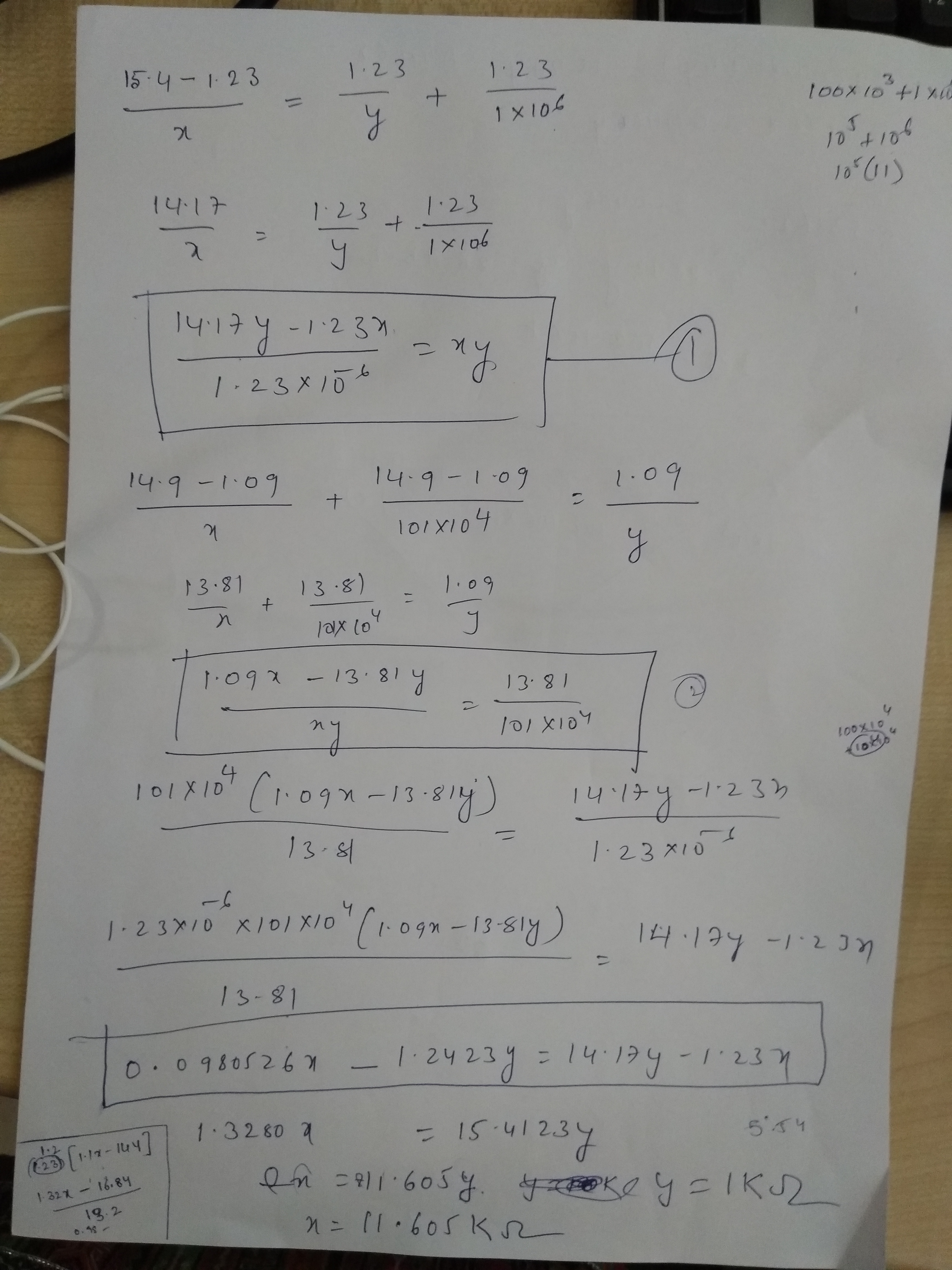
Can you please review the calculations and schematic attached and provide me your feedback.

 Thanks,

Ramya

  • Hello Ramya,

    If i understand your question correctly, you would want to latch off after UVLO event (after initial powerup).
    So you are trying to use, FLTb pin to pull down after UVLO?


    Regards,
    Kari.
  • Hi Kari,

    Thanks for the reply.

    You are correct, after UVLO event occurs i don't want to turn on the power till the battery is removed and charged and placed it back again or the battery voltage is stable.

    I have also done some calculations in excel as well as in paper. please find the attachments.

    one other important observation is that we are getting –ve values for R1 and R2.

    The formula in the excel Copy of R1 R2 calc-Formula.xls looks good and I didn’t find any error.

    I guess we are getting –ve resistor values because of the wide difference between the (Vs+ - Vs-) in both cases.

    The moment I put wide variation in the values in column D for Vs+ and Vs- I get –ve resistor value for application note data as well.

     If this design doesn’t suit our requirement after your review and confirmation, we need to look for other alternates. please suggest.

    Thanks,

    Ramya

  • Hi Ramya,

    I understand that you want to have hysteresis at the input battery rising and falling voltage. Ideally you want system to turn on at battery rising voltage of 15.4 V and turn off at falling voltage of 14.9 V or lower. Please let me know if this understanding of your system is correct.

    Based on this assumption, you don't actually need to use FLTb pin to dynamically change voltage at UVLO pin. Typical UVLO rising is set at 1.2V and UVLO falling is set at 1.1V. Now for a Vin of 15.4V, V(UVLO) of 1.2V and R2 of 10k we get R1 of 118.33k. 

    With these value of R1 and R2 we can calculate Vin at UVLO falling threshold.
    Using R1=118.33k, R2=10k, V(UVLO)=1.1V -> VIN comes out to 14.11V.

    Thus you have a hysteresis from 15.4V to 14.11V. 

    If you want to further increase the hysteresis, then the technique that you mentioned can be considered.
    Let me know if this solves your concerns.

    Thanks 

    Gaurang