This thread has been locked.

If you have a related question, please click the "Ask a related question" button in the top right corner. The newly created question will be automatically linked to this question.

Switching regulator VSENSE Connection- TPS54620

Other Parts Discussed in Thread: TPS54620

Hello,

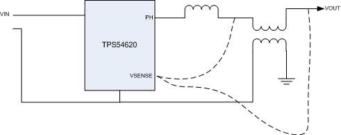
I am filtering the output of TPS54620 (for my 12V to 3.3V design) using a common mode choke. So now there is an interesting question as to where I need to connect VSENSE pin to? Is it to be connected before the choke or after the choke. Is it going to make any difference. The scheme is shown in the figure below.

  • You do not show all the other components,  but I recommend that you connect the voltage setpoint divider to VSENSe after teh output inductor and before the common mode choke.  Connecting after teh common mode filter would nominally give better regulation, but will make stabilizing the control loop difficult or ompossible. 

  • Hello John,

    First of all thanks for the clarification. Yes I had shown only the relevant components. 

    In the same scenario can you comment on one more point, how should I connect the signal grounds of the component? I have an option to connect the signal grounds (compensation network, feedback resistors etc) to the filtered ground. ie. after common mode choke. Will this also be having any similar issues, or is this a better choice?

  • I recommend that you do not connect to the filtered ground.  I connect the sensitive analog returns with a small copper pour area or 20-30 mil etch line.  Then connect them back to the main power ground copper pour area at a single point close to teh IC.  Due to the pinout of the device, you will need to make a separate connection for the RTCLK return.  That RT pin is sensitive.  Make sure to make those connection as short as possible.  See teh datasheet figure 56.