This thread has been locked.

If you have a related question, please click the "Ask a related question" button in the top right corner. The newly created question will be automatically linked to this question.

BQ24618: BQ24618 technical support

Part Number: BQ24618
Other Parts Discussed in Thread: BQ24610

Hello Team!

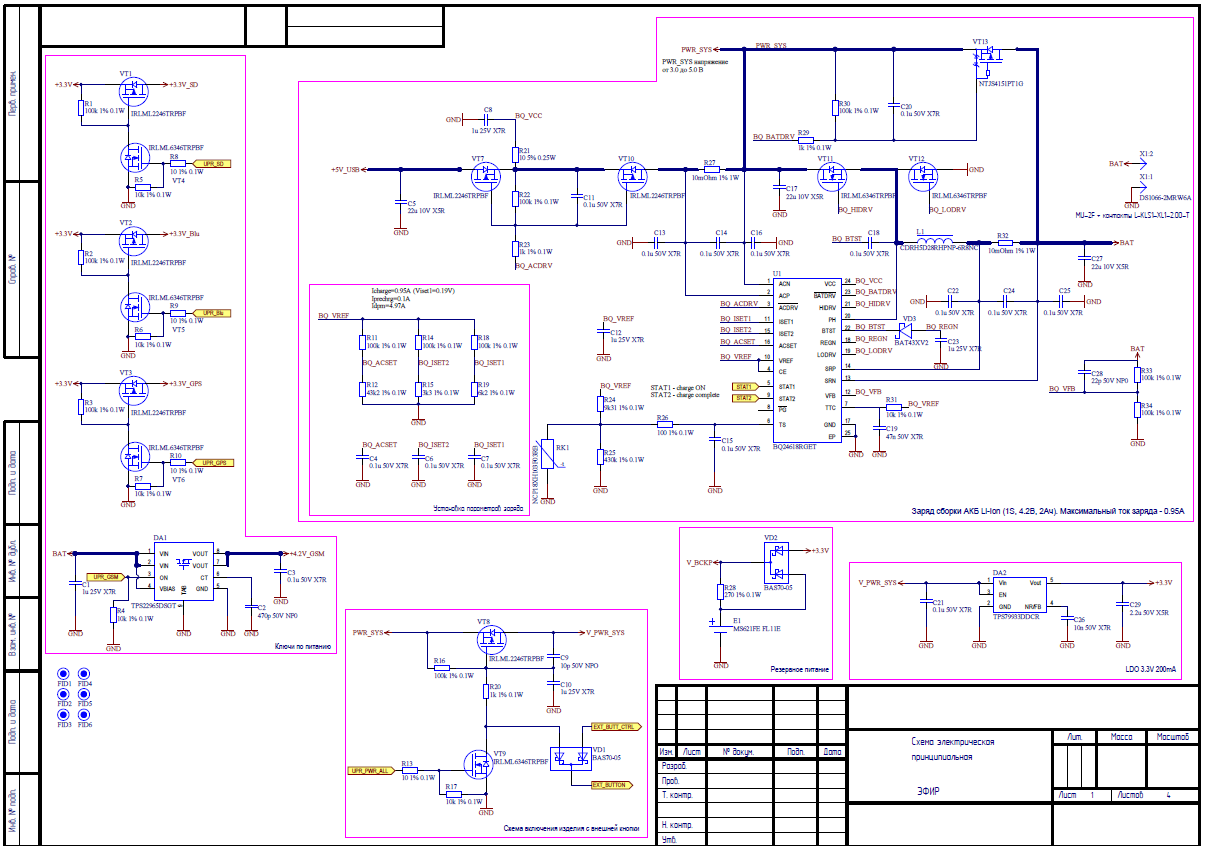
My customer uses BQ24618 in development Battery Charger. The piece of scheme is attached.

The essence of the problem in the following:

When a voltage of 4.09 V is reached on the battery, a cyclic shutdown of the charge process occurs.

In this case, the PG output is in the "ON" state, LED is working without flicker (during the troubleshooting process, the PG and STAT2 outputs were switched on in parallel, the last one is always in the OFF state), the output STAT2 is always "OFF" (LED is working), the output STAT1 cyclically changes the state from OFF to ON.

At the beginning of a cyclic shutdown of the charge process on an oscilloscope, I observe a drop in the input power of about 0.4V by the same pulses.

We thought that BQ24618 just turns off due to the voltage decreases below 4.7V, but the increase in the input voltage eliminated this cause.

Other actions that customer was doing:

1. VT7 and VT10 were changed;

2. VT11 and VT12 were changed;

3. Safety timer was turned off by pull up TTC to VREF;

4. VT7, VT10, VT13 were completely removed from the scheme. ACP and ACN was connected between each other, VCC connected to the input voltage, removed DA1 and VT8

The customer also changed parameters Icharge, Iprechrg. Parameter Idpm was decreased to 1A.

Parameters (voltages) on VREF, REGN, TS, VFB are normal.

Repetition of the problem on 3 boards with 3 different batteries

The customer suggests that the problem begins when the process changes from the state Fastcharge Current Regulation Phase to Fastcharge Voltage Regulation Phase.

On one of the boards (on which the outputs PG and STAT2 are not parallel, is supplied from the USB to the PC), the cyclical blinking of the LED on STAT1 was completed and the STAT2 LED is "ON" that signaled the end of the charget. At the same time, the voltage on the battery is 4.1V, at the input VFB 2.02V

Power is different: from the USB port to the PC, from the USB charger for the phone, from the laboratory PSU with power supply from 5 to 7 V. Charging the battery LiIon 3.7V 2000 mAh.

Could you please help resolve this problem?

Thanks in advance!

Best regard

Aleksandr Morozov

  • Aleksandr,

    Could you please provide the followings?

    1. When the device stops charging @ VBAT=4.09V, what was ACN pin voltage?
    2. Is there gauge or protection IC in between the charger BAT output and the battery? Or does the battery have built-in gauge/protector?

    Thanks,

    Ning.
    Please click "This Resolved my issue" button if this post answer your question.
  • Aleksandr,

    We haven’t heard back from you for a while, the thread is considered solved and closed.

    Thanks,
    Ning.
    Please click "This Resolved my issue" button if this post answer your question.
  • Ning, Hi!

    I apologize for the delayed response.

    I connected with my customer and get some details.

    The all batteries have integrated protection boards against deep discharge.

    The customer tried to connect without boards and it was not successfully.

    Also the customer did the following changing:

    -replace HIDRV LODRV to SIS412  (does not helped)

    -bq24618  was replaced to bq2461 (the customer does not change anything else according to the scheme) and power supplied by laboratory PSU. The only difference is that when connected the battery is discharged, the circuit starts normally and starts charging, but when approaching the charged state, the battery also goes into cyclic mode

    The foto of waveforms is here.

    Regards

    Aleksandr Motozov

  • Aleksandr,

    What is bq2461?

    Thanks,

    Ning.
  • Ning,

    I'm sorry. bq24618 was replaced to bq24610

    Regargs

    Aleksandr
  • Aleksandr,

    Unable to access the waveforms. Please connect the battery to the charger directly (no protection board in between) and do not apply any system load. Then could you please measure the following pin voltages?
    VCC, ACP, ACN, /ACDRV, ISET1, ISET2, ACSET, VREF, CE, STAT1, STAT2, TS, /BATDRV. REGN, SRP, SRN, VFB
    Please also provide the part number under test and VBAT, IBAT (No system load)

    Thanks,

    Ning.
    Please click "This Resolved my issue" button if this post answer your question.
  • Hi,

    We haven’t heard back from you for a while, the thread is considered solved and closed.

    Thanks!

    Please click "This Resolved my issue" button if this post answer your question.