This thread has been locked.

If you have a related question, please click the "Ask a related question" button in the top right corner. The newly created question will be automatically linked to this question.

TPS61021A: Questions about TPS61021A device

Part Number: TPS61021A
Other Parts Discussed in Thread: TPS61021EVM-723

Hi,

I am evaluating the TPS61021A device by obtaining the evaluation board.
The evaluation board is TPS61021EVM-723.
So I have some questions about how to use the device.

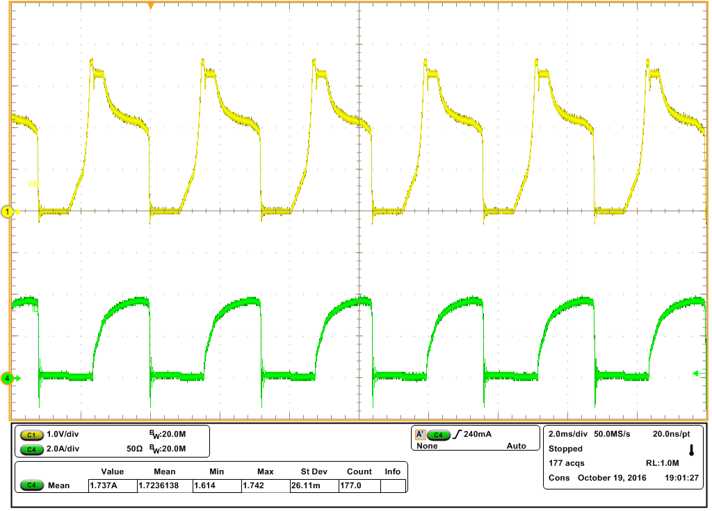
· What is the variation of fsw? (PWM is in a stable state)

· Is the value of Rθja on the evaluation board 71.1°C / W? Or does θJa change in EVM?
  I believe that board area will affect.

· Coil selection, is it suitable for selection from 0.33uH to 1.0uH / ± 30%?
  What is wrong if 1.0uH + 30% is exceeded?

· It is a question about Cin. If there is ringing to Vin, there is addition of a tantalum capacitor, but is there a need for low ESR for this tantalum C?
  What is the value of ESR required for ESR?

· What is the current value of the branch point between PFM and PWM? (When Vout = 3.5 V)

· It is a question about behavior of short circuit protection operation.
  When Vout becomes 1.6 V or less, the current is limited, and if Vout falls below 1.0 V, there will be a limit of 100 mA.
  What is the relationship with Ilim = 4.3 A? Is there a diagram showing Vout and current limit value?

(specification)
Vout : 3.5V
Vin : 1.5V to 3.5V
Iout : 0.7Atyp

Best regards,

  • Hi Kaji@PAN,

    The expert supporting this device is out of office. She will reply you when back to office.
  • Dear Sir,

    Please check my reply below:

    • It depend on the load range. If the load is high enough and it is always works in the PWM mode. Then the fsw is fixed at around 2MHz when Vin >1.5V

    • Rθja is tested according to the international standard. Not on the EVM board. The board area will affect. But we can sure that the thermal on the EVM board is OK under the rated output capability.

    • Suggest you select a inductor less than 1.0uH. 0.47uH inductor is preferred. If the inductance exceeds 0.47uH. There will be stability issue.

    • The ESR of the tantalum capacitor helps reduce the ringing. You can choose an ESR>50 mhom tantalum capacitor or EL cap. Actually, if the input wire in your system is not long, sometimes there will be no ringing at all.

    • it is around 500mA at Vin=2.4V

    • 100mA has nothing to do with the 4.3A. 100mA only active when Vo is lower than 1.6V.
  • Thank you for your reply.
    I would like to ask a few questions about your answer.

    •It depend on the load range. If the load is high enough and it is always works in the PWM mode. Then the fsw is fixed at around 2MHz when Vin >1.5V
    (Additional questions)
    Is there data with variation of 2 MHz? I would like to know MIN and MAX at 2 MHz.
    When there is no data, how much range of variation is assumed?
    There is no need to guarantee this variation.

    •Rθja is tested according to the international standard. Not on the EVM board. The board area will affect. But we can sure that the thermal on the EVM board is OK under the rated output capability.
    (Additional questions)
    I understood that θja of the evaluation board is also calculated at 71.1 °C/W.
    Is this my idea correct?

    •Suggest you select a inductor less than 1.0uH.
    0.47uH inductor is preferred.If the inductance exceeds 0.47uH. There will be stability issue.
    (Additional questions)
    If it exceeds 0.47 uH, does it affect stability?
    Is it not stable at 1.0 uH?

    •100mA has nothing to do with the 4.3A. 100mA only active when Vo is lower than 1.6V.
    (Additional questions)
    I think that the function of output short circuit is current foldback.
    Although the normal current limit is 4.3 A, the limit value of 4.3 A drops from the output voltage below 1.6 V. When the output voltage is 1.0 V, the current limit is constant at 100 mA.
    Is my opinion correct?
    If my opinion is correct, is there data on how the current limit value from 1.6 V to 1.0 V changes?

    Best regards,

  • Dear Sir,

    Please check my reply below:

    It depend on the load range. If the load is high enough and it is always works in the PWM mode. Then the fsw is fixed at around 2MHz when Vin >1.5V
    (Additional questions)
    Is there data with variation of 2 MHz? I would like to know MIN and MAX at 2 MHz.
    When there is no data, how much range of variation is assumed?
    There is no need to guarantee this variation. --> within +-15%

    •Rθja is tested according to the international standard. Not on the EVM board. The board area will affect. But we can sure that the thermal on the EVM board is OK under the rated output capability.
    (Additional questions)
    I understood that θja of the evaluation board is also calculated at 71.1 °C/W.
    Is this my idea correct?--> We usually use ψJT instead of the Rθja to calculate the junction temperature. Use a thermal detector test the temperature on the top of the IC, then use ψJT calculate the junction temperature.

    •Suggest you select a inductor less than 1.0uH.
    0.47uH inductor is preferred.If the inductance exceeds 0.47uH. There will be stability issue.
    (Additional questions)
    If it exceeds 0.47 uH, does it affect stability?--> I made a mistake it should be higher than 1uH.
    Is it not stable at 1.0 uH? --> When >1.0uH, its hard to compensate. But may still stable.

    •100mA has nothing to do with the 4.3A. 100mA only active when Vo is lower than 1.6V.
    (Additional questions)
    I think that the function of output short circuit is current foldback.
    Although the normal current limit is 4.3 A, the limit value of 4.3 A drops from the output voltage below 1.6 V. When the output voltage is 1.0 V, the current limit is constant at 100 mA.
    Is my opinion correct?
    If my opinion is correct, is there data on how the current limit value from 1.6 V to 1.0 V changes? --> In fact, when the Io is high and the Vo drop to below 1.6V, the output is a pulsed current instead of the continuous current. when Vo drops below 1V, the Io is a constant around 100mA current.  Please check the attached waveform.

  • Thank you for your reply.
    I appreciate your detailed explanation.

    Finally I would like to ask another question.

    Is there data with variation of 2 MHz? I would like to know MIN and MAX at 2 MHz.
    When there is no data, how much range of variation is assumed?
    There is no need to guarantee this variation. -> within + -15%
    (Contents of question)
    Is the above value of ± 15% when the ambient temperature is 25°C?
    Or is it a value over the whole temperature range?

    Best regards,

  • Hi Sir,

    This is of the whole temperature range.