


Our school group is designing a tone generator for a class project. We ran the WebBench tool to help us specify parts for the voltage regulation circuit and decided to go with the TPS561208 switcher to produce a 3.3V output. We followed the suggested schematic and PCB layout (see attached) from the TI datasheet. We got our PCB built and started soldering on components this week. We gave it an initial test and our only problem seems to be with the 3.3V Switcher. We did a simple finger test on the component and it gets really hot on startup and then switches off. We have checked the schematic many times, read through the datasheets, checked for solder bridge shorts, etc and found nothing.We replaced the TPS561208 with a new part and the problem was repeated. We built just the 3.3V switcher schematic components on a separate board to isolate the problem and the problem was repeated. The component, new, out of the packaging reads about 300K ohms output to ground. After it has been briefly given power (6 or 7 Volts only, full voltage will be 12 V) this is reduced to 3 to 6 ohms to ground. When the part is removed from the board there is no longer a short between the 3.3V and ground plane. We took some data with the oscilloscope (see attached). You can see the switcher turns on and comes up to the full 3.3V output, but then overheats and cycles on and off a bit before it dies.
Our current point of contention is the ESR of the passive components around the switcher. We only spec'd the TPS561208 from the WebBench tool and did not realize the passives might be critical also. We are using a 3.3uH inductor with about 70 miliohms ESR (TDK VLCF4020). The coilcraft inductor in the WebBench tool was only about 18 miliohms ESR. We chose X5R caps, but the ESR for them is not specified in the datasheets. Could high ESR passives cause this problem?
Any help is appreciated. If I left anything out and you need more specifics, please ask.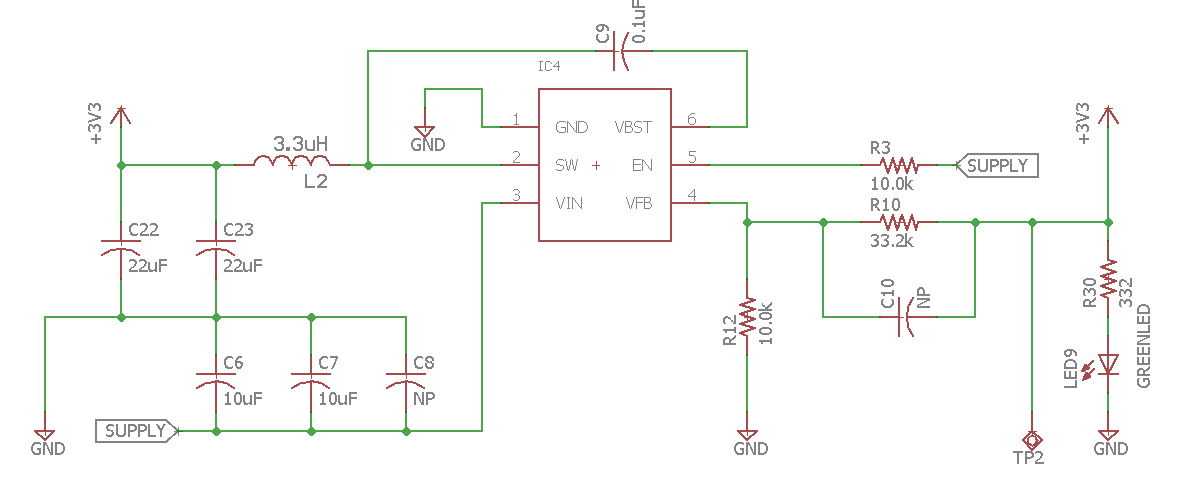
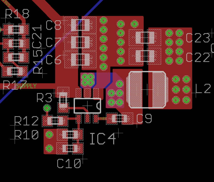
It is a 4 layer PCB. The blue is on the bottom side. There is a ground plane and a 3v3 power plane in between top and bottom.
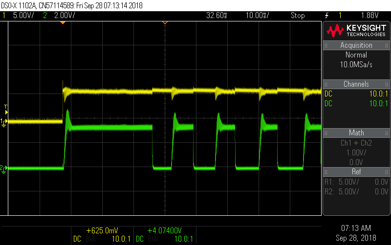
This was taken after the fault occurred. The yellow is input. The green is output.
Yellow input, Green Output
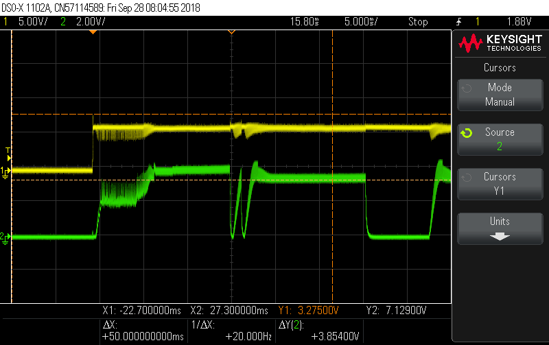
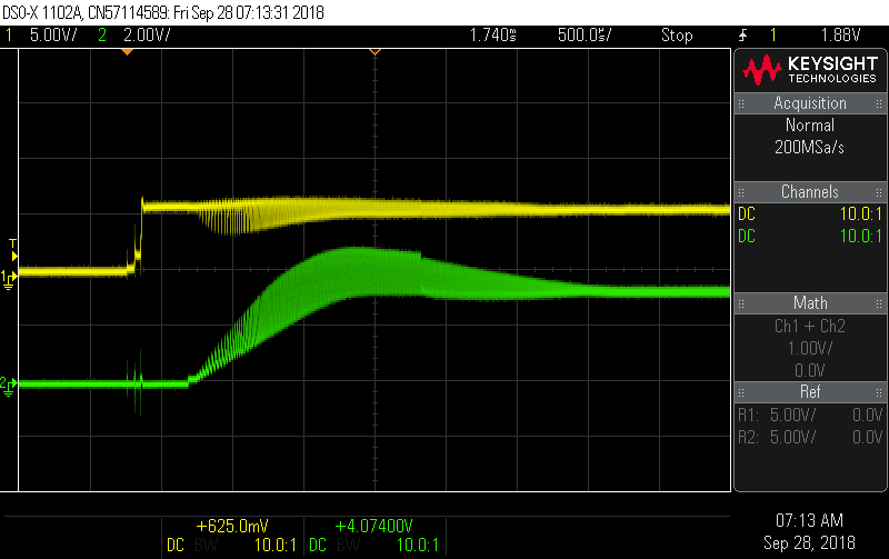
Yellow input, Green output. This was taken with a second, new chip. This should show the fault occurring.
