Other Parts Discussed in Thread: TINA-TI,
I have to confess my ignorance in this post upfront!
This topic has to do with slope compensation of a buck converter with 70% duty cycle.
One can read & I have been doing this for several years until now, but did not have any meaningful rebuttal of the received truth because what I see does not match with what is stated.
For starters, all baseline CCM/PCM is stated to require slope compensation of Mc .
Magically if Mc=M2, down slope of the "inductor current", stability is achieved in 1 cycle.
A lot of ink has been spent on Mc, M2 etc.
But the solution always given to "add a slope compensation" from anywhere BUT the inductor current. In almost all literature, one is advised to just throw in after some incomprehensible Algebra using Rs, Gi, Ri, Km etc. etc...in the end one adds ramp of the oscillator to the sensed current.
WELL THAT ramp has no connection with the inductor down slope! Nor any connection with what has been derived as "down slope"
besides, the switch has been already turned off. So what part in the control section has any contribution to make in compensating for Subharmonic oscillation?
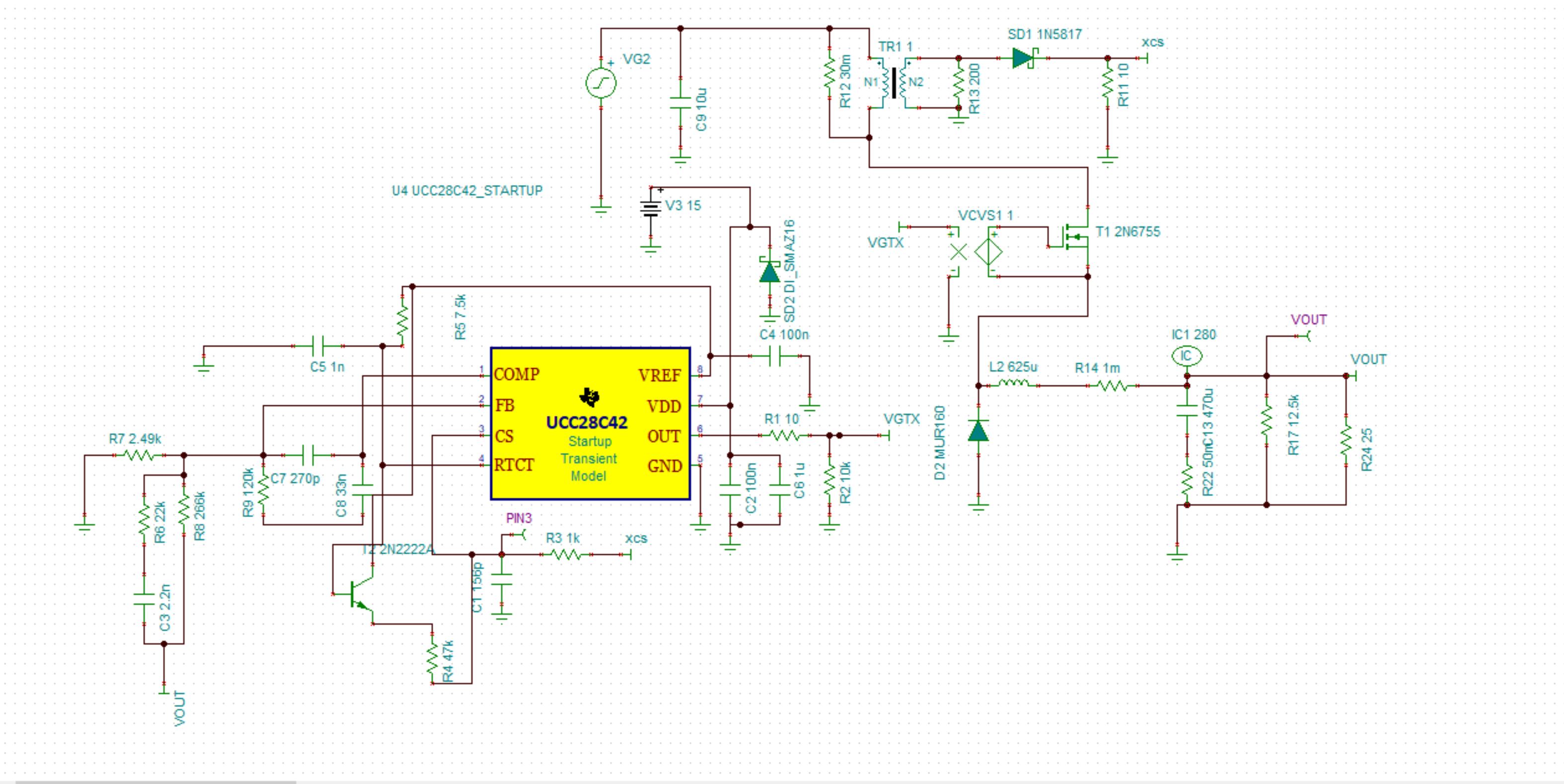
Pl see the TINA-TI screen shot: the values of the compensation cannot be derived from SLUA301 not from SLV450. In real circuit, this is a very very slow circuit to respond to transients.
Does it mean that getting 270V from a 350V is not theoretically possible using a buck converter?
I suspect, the model does not give proper values because "slope compensation" --if the SPICE model of UCC28C43 contains the artifact to response to compensation- is not really being added correctly. Even though we are doing exactly what is written in the cited materials.
So how do we get to a decent cross over freq of this circuit ?
W: we do have an ACS723 after the inductor - but its BW is 80kHz while switching is happening at 200 KHz. We have it so shut down in case of short circuit.
Can that be used for "Slope comp"?
Any help will be highly appreciated. '