This thread has been locked.

If you have a related question, please click the "Ask a related question" button in the top right corner. The newly created question will be automatically linked to this question.

TPS65218D0: What difference between this new version and the old version?

Part Number: TPS65218D0
Other Parts Discussed in Thread: TPS65218

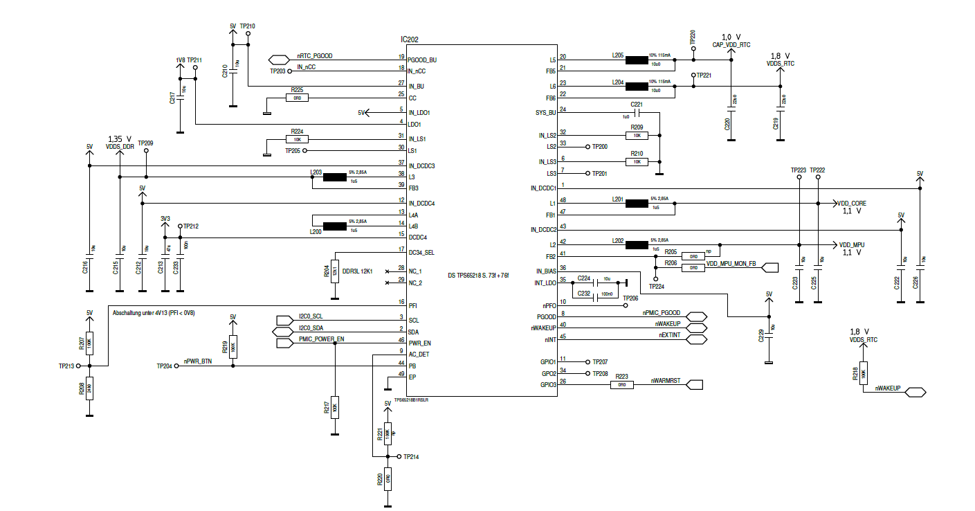
I have a different behavior if I send the poweroff command from my Linux System. With the former TPS65218B1 mounted on the same board the PMIC goes in the OFF state. The TPS65218D0 goes in the RECOVERY state (reboot after 500 ms). What could be the reason for this behavior? Is a new entry in the device tree required. My board is similar to the BeagleBoneBlack.

  • Hi,

    I have assigned your request to responsible Applications Engineer and we will get back to you as soon as possible.

    Regards,

    Murthy
  • Kai,

    Did you have any workarounds implemented on your board for the TPS65218 -B1 version? For example, did you have an extra capacitor or diode added to the output of DCDC4? These workarounds are not required for TPS65218D0 and should be removed.

    In addition to the DCDC4 improvements that allow a simpler BOM, the STRICT=1b behavior of the device has been improved (narrower tolerance window for VPG and VOV). The impact in your system could be that creating a tighter tolerance window has created a VPG fault during the ACTIVE to OFF transition.

    You can check for this in a couple ways:
    1) Digital - change STRICT=1b to 0b in volatile memory by writing 0b to bit 2 of register 0x13 (CONFIG1).
    2) Analog - monitor PGOOD and PGOOD_BU on a scope to see which one of these goes low unexpectedly. The ripple voltage on DCDC1-4, LDO1 must be monitored if PGOOD drops and the ripple on DCDC5-6 should be monitored if PGOOD_BU drops.

    If changing STRICT bit to 0b fixes the issue, it is possible to re-write this value in the EEPROM of the device which stores the Register Map reset values.
    If you do not want to fix it in digital, the analog fix would be adding some additional capacitance to smooth out the ripple which causes the fault.

    Thanks & Best Regards,
    Brian
  • Hi Brian,

    my schematic is based on the suggestion in the data sheet of TPS65218B1:

     I checked the signals PGOOD and PGOOD_BU, but the behavior of the signals seems to be normal. There is only the drop in the 500ms break. The suggestion of change STRICT=1b to 0b in volatile memory I didn't try until now. An additional capacitor of 47µ on DCDC4 didn't help.

    What is with the signals AC_DET and PWR_EN in my schematic, is the wiring OK? PWR_EN goes to PMIC_POWER_EN of the Sitara.

    Thanks,

    Kai

  • Kai,

    As long as R221 is not populated, the AC_DET is okay. Section 5.3.1.16 AC_DET Input (AC_DET) in the TPS65218D0 datasheet recommends AC_DET = GND for non-portable applications.

    PWR_EN is controlled by the processor PMIC_POWR_EN signal, so this should not be an issue.

    Please measure PWR_EN and PB (push-button) input with a scope to make sure these signals are not causing the problem. In addition, you might want to look at GPIO3 to make sure this signal did not cause a warm reset on DCDC1 or DCDC2.

    Also, it appears you are not using any load switches LS1-3. It could be an issue that you are not using Load switch 1 and the input is grounded, as LS1 is normally powered from DCDC3 and is used to enable/disable DDR power.

  • Brian,

    here is the scope result (yellow: PB, green: 3V3 (DCDC4), blue: GPIO3, pink: PWR_EN). With R221 populated (AC_DET=High) and R220 not populated I get the same behavior as with TPS65218B0, please see the second scope result. This would be OK for my application. In Section 5.3.1.16 AC_DET Input (AC_DET) is described as follow:

     "In a non-portable system, the AC_DET pin may be shorted to ground and the IC powers up whenever system power is applied to the chip." --> So the IC would never goes in the OFF-state. A falling edge signal on AC_DET seems not to be necessary with the new revision of TPS65218.

    Best regards,

    Kai

  • Kai,

    Thank you for taking the extra step to debug and show me your results!

    As long as you are OK with using a Push-Button press (PB toggle hi-lo-hi) to power-on from the OFF state then this seems like the correct method for you and your system.

    Thanks,
    Brian