This thread has been locked.

If you have a related question, please click the "Ask a related question" button in the top right corner. The newly created question will be automatically linked to this question.

TPS53319: Schematic Check - slow transient performance

Part Number: TPS53319

Hi guys,

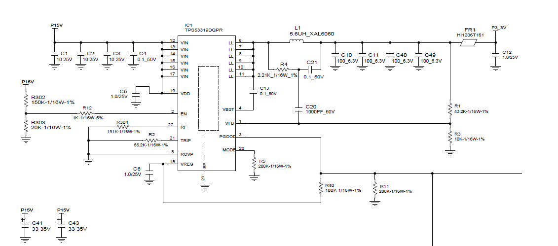
I am asking a related question to something I posted a while ago. My customer designed two supplies with the TPS53319, where the initial component values were picked using webench and then modified as needed for an expected load current. One supply, 15V to 1V @ 9A is working well. The other supply, 15V to 3.3V @ 4A isn't. Now this supply was overdesigned and the load current ended up only being 1.5A. However, whenever there is a load step on the 3.3V supply (in the form of switching in a 47uF capacitor as a load) the transient response is slow and the input dips down to 2.8V

Can you guys take a look at the schematic and let me know if there is anything majorly wrong, and how you'd recommend we change it?

Thanks,

Brian 

  • Hi Brian,
    Would you please explain "in the form of switching in a 47uF capacitor as a load"? What is the load step from and to? Was the 15V to 1V and 15V to 3.3V have the same layout? Just to verify, is the input dropping from 15V to 2.8V during the transient response?
    Thanks.
    Amnat
  • Amnat,

    The capacitor is empty, the power supply is at no load steady state, and then a switch is essentially closed that puts a 47uF cap in parallel with the output as a load step. Im not sure what the current demand looks like exactly during this inrush phase, but I guess I can say that one supply can handle it (the 1Vout) and the other cannot (the 3.3Vout). The output is supposed to remain regulated close to 3.3V, but instead droops down to 2.8V.

    I can ask for the layout of both power supplies, and ask for perhaps a current waveform if they can measure it, but does the control loop of those two supplies look alarmingly different, and can you recommend a change to the L or the compensation RCs?

    I know I'm not give you guys a ton here, but any comments you can make armed only with the schematic would help!

    Thanks,
    Brian
  • Hi Brian,
    Thank you. The schematic looks good. The inductor ripple is reasonable for the ICCMAX=4A design. We typically set the ripple to about 30% of the ICCMAX. I've calculated the ripple injection value based on your schematic to be ~20mV. Can you please try changing R4 to 4.99K which should be ~10mV of injected value? This may help speed the transient response up.

    One more thing, what is the VOUT regulated value in AUTO-SKIP mode and FCCM mode?

    The waveform will be very helpful. Please make sure if they can use the electronic load instead of the 47uF capacitor during the load transient test. I just want to make sure that we are within the current limit setting.