This thread has been locked.

If you have a related question, please click the "Ask a related question" button in the top right corner. The newly created question will be automatically linked to this question.

TPS63001: I need help in checking my design, tests show problem with the regulator

Part Number: TPS63001

Hi to everybody,

I've tried to add the TPS63001 to my PCB following the rules found in the datasheet buf unfortunately when it was time to solder and test it doesnt work..

The board is powered by a single cell li-on battery (in the PCB i have also included the IC for over discharge/charge) and normally the overall consume is 100mA with peak of 250mA (let's say 400 eventually for further modifications)
I've tried the complete soldered board and for comparison another one but with only the chip and the components necessary soldered. But the behaviour is the same: when i plug the power supply at 3.0v the power supply reach the limit value of current setted at 400mA (no load attached) and the INPUT voltage remain 1.7v as the output.... before continuing testing others voltage or increment the current in input I would ask help for this strange behaviour.

ps. when powered i can hear a buzz noise coming from the inductance (or the capacitors maybe?)

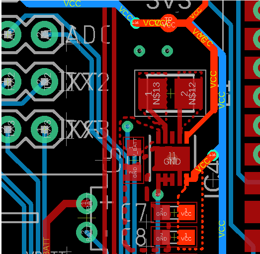
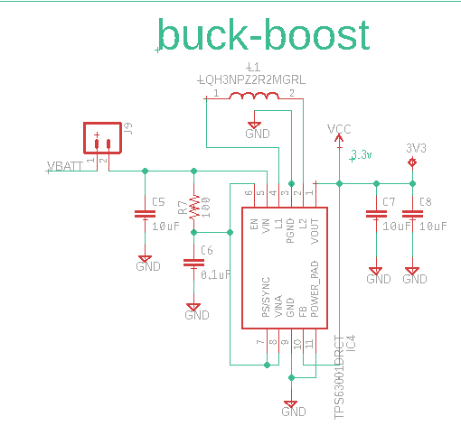
here follow the schematic and the PCB layout:


ADDITION:
the inductance comes from Murata ad has a Maximum DC Current of 1.73 A and Maximum DC Resistance of 104.4 mOhms,

the effective point when the power is connected to the board is quite far away (4cm more or less) it's a problem?

Thanks,

Cristian

  • Hello Cristian,

    On your layout, I cannot see a connection from the VOUT pin to the FB pin. Please point me to this connection. Please check if the problem is gone when you add this connection close to the IC.

  • Hi,

    Thanks for the reply,

    You are right, the connection from Vout (for me the net is renamed VCC) and FB is far away from the IC.

    As you can see from the new image the net Vout(for me VCC) is highlighted.

    I can try with a wire to make a shorter connection on monday, did you think that there can be others problem with my layout?

  • Hello Cristian,

    i tried to replicate your issue and was not successful. I could reproduce a similar behavior, when using a 4quadrand power supply (with force/sense) and connecting force/sense to a different PCB with high cap.

    In your layout i can see, that the output caps (C7/C8) are not placed optimal. They should be as close as possible to VOUT (pin 1). Try also to have a planes(or thicker traces) for Vout/Vin instead of thin traces.

    regards,
    Julian
  • Hi,


    Sorry for take so long, I've had others issues.
    However, Brigitte thankyou very much for the help!

    The problem was in the long connectio from FB to VOUT. I've done a short with an external cable and It works great!
    There are occasionally problems at the start-up when the IC consumes high peak of current but then it stabilizes at 40mA (If i detach the load only for the startup time the issue disappears)

    Thank you!

    Best regards,
    Cristian